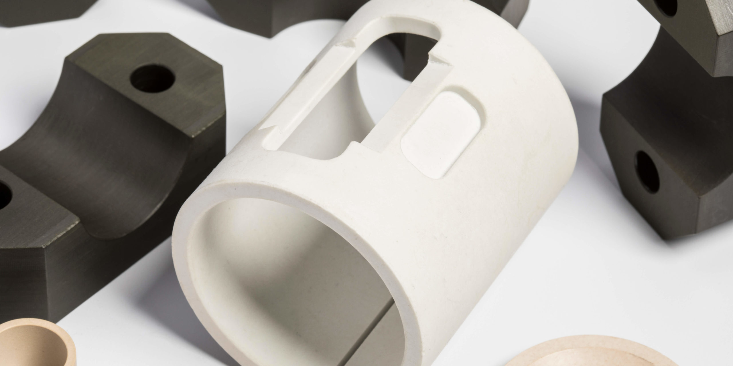
Sustainability conversations in engineering tend to focus on the big ideas, such as electrification, renewable energy sourcing, and material recycling, but all at the macro level. On the other hand, component-level design decisions, like bearing selection, are rarely part of that conversation. And this is despite them offering measurable, cumulative impact.
This article will introduce polymer plain bearings as an underexamined contributor to sustainability performance.
Weight Reduction and Energy Efficiency
Polymer plain bearings are substantially lighter than steel bearings of comparable size and load capacity. In mobile and rotating equipment, that weight reduction translates directly into reduced energy consumption over the equipment’s operating life. Now this is not a marginal, one-time engineering benefit: the weight savings from using a polymer where possible will compound across production volume and service life. This makes the cumulative energy impact larger than it initially appears. The cumulative energy impact is most obvious in mobile/dynamic equipment.
Elimination of Lubricants
Many plain polymer bearings are self-lubricating (e.g., PTFE, PEEK, and UHMW PE) either inherently or through the use of solid lubricants incorporated into the bearing material. Such designs do not require grease or oil. This can eliminate a recurring environmental and operational burden by reducing lubricant consumption, disposal, and contamination risks.
Keep in mind that every eliminated relubrication interval reduces petroleum-based lubricant use, packaging waste, and the handling/disposal requirements associated with spent lubricant. In addition, this reduces the risk of environmental contamination in food, water treatment, and outdoor equipment applications, where lubricant leakage incurs both environmental and regulatory costs.
The elimination of lubricants through polymer bearings provides an operational sustainability benefit, not just an environmental one. Fewer maintenance interventions for lubrication also reduce associated labor, transportation, and waste streams.
Recyclability and Service Efforts
Certain engineering thermoplastics used in bearings can be recycled at the end of life, including PEEK, POM, and UHMW PE. This is in direct contrast to composite or multi-material metal-bearing assemblies, which are significantly more difficult to separate and reclaim. Keep in mind, of course, that not all polymer-bearing materials are equally recyclable, and reinforced or filled compounds may complicate recycling. This advantage is dependent on the type and grade of polymer selected.
Service life is also a relevant factor: in corrosive, washdown, or moisture-exposed environments, polymer bearings often outlast steel alternatives that require corrosion protection or more frequent replacement. This has the potential to extend the component’s useful life while reducing material turnover.
Where the Sustainability Case Has Limits
There are boundaries to the sustainability capabilities of plain polymer bearings, however. They are not universally superior. They do have operating envelopes that involve factors such as load capacity, operating temperature, and speed limitations. This means they are not an appropriate substitute for every bearing application. As such, replacing metal bearings with polymer alternatives requires careful evaluation rather than blanket substitution. And while the sustainability case is compelling, it depends on correct application.
Conclusion
Sustainability in engineering is often achieved through cumulative, component-level decisions rather than singular large-scale initiatives. And that includes the choice of bearings and bearing materials for dynamic machinery and other dynamic applications. Advanced EMC is your resource for engineers evaluating whether a polymer bearing is a viable, sustainability-conscious alternative for your application. Contact us today!
You may have been in this situation: a bearing on a VFD-driven motor design has failed with no obvious overload, contamination, or lubrication issues. Upon teardown, fluting is evident. This article discusses what causes this problem, how to diagnose it correctly, and a basic solution hierarchy to mitigate the effects of fluting.
Why VFDs Cause This Problem
VFDs (Variable Frequency Drives) use PWM switching (typically IGBTs) to synthesize the output waveform. The problem lies in fast-switching edges, not in the source voltage itself.
Where the Voltage Comes From
In short, fast switching (i.e., high dV/dt) combines with the motor’s parasitic capacitance to create a common-mode voltage. That voltage is referenced to the ground rather than between phases. Because the three-phase voltages do not sum to zero instantaneously on switching transitions, a residual common-mode component appears on the motor shaft. Note that this is inherent to the PWM TFD topology and is not a sign of a bad drive; it can occur even in systems that were correctly installed.
Construction of the Capacitor Network
The motor behaves as a set of parasitic capacitors: stator winding-to-frame, rotor-to-stator, and, most importantly, rotor-to-shaft-to-bearing. Electrically, the bearings sit between the shaft and the housing, separated by a thin film of lubricant. The lubricant, usually grease or oil, acts as a dielectric. As such, it makes the bearing itself act as a capacitor in the circuit.
Arcing Mechanism
The common-mode voltage charges the bearing’s lubricant film like a capacitor plate. As the voltage rises, it will eventually exceed the dielectric strength of the lubricant. The film begins to break down, and the charge stored in the dielectric film discharges as a spark across the rolling element/race contact. The effect is the same as a micro-EDM (electrical discharge machining) event (having far more impact than a simple case of resistive heating).
While each discharge event is tiny, on the order of microseconds with low energy, it is repetitive. It can happen thousands of times per second, depending on shaft rotation and switching frequency.
There are three commonly accepted current paths involved in the arcing mechanism: (1) shaft voltage discharge/EDM currents, (2) high-frequency currents driven by flux asymmetry, and (3) rotor ground currents.
Visible Damage
Each of these thousands of discharge events removes a microscopic amount of material. Again, this is essentially the same physics as EDM machining, just unintentional and uncontrolled. Because the rolling elements pass over the same race positions repeatedly, damage will concentrate at those repeat contact points rather than being randomly distributed. Over time, which can range from weeks to months depending on severity, the repeated point damage accumulates into visible fluting. Fluting is a series of transverse grooves/ridges spaced at a pitch related to rolling element spacing.
Why It is Worse in the VFD Era
Older fixed-speed motors ran on sine-wave utility power with no PWM switching, and had no common-mode voltage source to speak of. However, modern IGBT-based drives switch much faster than earlier drive generations, which increases dV/dt and worsens the effect. In a parallel trend, EV traction
motors push switching frequency even higher, which is part of why this issue is intensifying rather than fading as drives get more advanced
High Risk Applications
Certain applications are considered high risk for electrical fluting and EDM pitting. These include …
Larger motors / higher power ratings (more capacitive coupling)
Longer cable runs between drive and motor (affects reflected wave and common-mode behavior)
No shaft grounding provision
Standard (non-insulated) bearings on both drive-end and non-drive-end
Grease type/film thickness — thinner, more conductive films behave differently than thick, highly insulating ones, and neither is automatically safe
Diagnosis — Fluting vs. Other Failure Modes Under a Scope
Other failure modes that can be mistaken for fluting include true and false brinelling, as well as corrosion pitting.
The Appearance of Fluting
When observing fluting damage. there will beparallel, closely spaced transverse grooves or ridges running across the race width and perpendicular to the direction of rolling. This type of damage is often referred to as having a “washboard” or “corrugated” appearance. Also note that the spacing of the grooves often correlates with rolling-element spacing/pass frequency, which can serve as a diagnostic clue. As to the location, fluting can appear on both inner and outer races; the distribution and severity of the fluting between drive-end/non-drive-end can hint at the current path.
Under magnification, you will see individual craters or pits within the grooves, the actual EDM discharge sites, often described as looking like tiny volcanic craters when viewed at high magnification (SEM-level). In addition, it is common to see discoloration that may take the form of a gray, frosted, or matte-etched appearance rather than a bright/polished one. This is due to localized micro-melting and re-solidification from each discharge. Further, the edges of pits tend to be irregular and melted-looking.
Contrast: True Brinelling
True brinelling, often mistaken for fluting, is a distinctly different type of bearing damage that is caused by static overload or impact (heavy shock load while stationary). This is a mechanical failure, not an electrical one. True brinelling looks like discrete, smooth-walled indentations spaced at rolling element pitch, but each is a single clean dent — no fine internal texture, no discoloration/melting. This type of failure can be diagnosed by dents that match the static rolling-element spacing exactly and show no vibration/fretting content between them, because the bearing was not rotating when the damage occurred.
Contrast: False Brinelling
False brinelling, also known as fretting, is caused by micro-vibration without rotation and often happens during shipping/transport damage or standstill vibration near an operating machine. It exhibits shallow, polished or burnished wear marks often with reddish-brown fretting corrosion debris (iron oxide) at the contact points. It differs from fluting in that it has characteristic red/brown oxide debris and a polished surface texture with no crater pitting under magnification.
Contrast: Corrosion pitting
Corrosion pitting is caused by moisture ingress, chemical attack, or inadequate corrosion protection, but is not related to load pattern or electrical activity. It also has pitting, but it is
randomly distributed rather than following rolling-element pitch or a directional groove pattern. The pit shapes tend to be irregular and do not align in the orderly rows fluting produces. Corrosion pitting can be differentiated from fluting because it is not correlated with rolling element spacing and is often accompanied by broader surface rust/staining beyond the raceway contact zone.
Diagnosing Fluting
Here is a simple diagnostic decision path for the diagnosis of fluting:
Is the damage pattern regularly spaced and directional (grooves) → suspect fluting or true brinelling
Under magnification, is there micro-pitting/crater texture and dark/etched discoloration → fluting; smooth without craters → true brinelling
If damage is polished with reddish oxide debris and no deep grooving → false brinelling
If damage is randomly distributed with no pitch correlation → corrosion pitting
Experts also recommend checking shaft voltage with a multimeter or oscilloscope as a confirming (not just visual) diagnostic when fluting is suspected. Its presence ties the root cause to the physical evidence rather than relying on appearance alone.
Tips for Diagnosing Fluting
In practice. basic magnification (10–30x loupe) is often enough to distinguish fluting from brinelling in the field. However, SEM imaging is the gold standard for confirming EDM-style micro-cratering when there is any ambiguity or when documenting a warranty/failure investigation. Finally, remember that a brush or contact probe riding on the shaft, feeding a high-voltage differential probe on an oscilloscope, remains the complementary electrical-side check that confirms the root cause rather than just the symptom.
Solution Hierarchy for Fluting
Why hierarchy? No one solution solves all the problems involved. In short, insulated bearings block the current path, grounding rings divert it, chokes reduce it, and each addresses a different one of the three current types (shaft-voltage discharge, high-frequency circulating current, rotor ground current). Choosing one option to protect a bearing location can simply push the current elsewhere.
Insulated Bearings
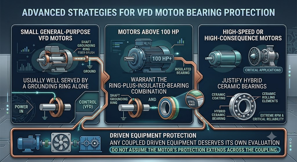
Insulated bearings are usually the first line of defense. A plasma-sprayed alumina coating on the inner or outer ring creates a dielectric barrier between shaft and housing. This approach typically delivers insulation resistance in the tens to hundreds of megohms with a dielectric withstand rating around 1500V DC. At roughly a 200–300% cost premium over a standard bearing, insulated bearings are a meaningful but manageable upgrade, most commonly specified at the non-drive end. In contrast, the drive end gets a grounding ring instead.
The catch is that insulating one location pushes current toward the uninsulated bearing, so this option is rarely used on its own. In addition, the coating can degrade from handling damage or moisture bridging the insulation layer. Periodic insulation-resistance checks belong in the reliability program, not just the commissioning checklist.
Hybrid Ceramic Bearings
Hybrid ceramic bearings take a more fundamental approach: steel races are paired with silicon nitride rolling elements that simply cannot conduct current across the rolling contact. This forms a broken circuit that is categorically more robust than a coating. Hybrid ceramic bearings are often priced at a 400–600% premium. It does, however, earn its cost on high-speed or high-consequence motors, or anywhere coating durability is a real concern. The same “current finds another path” caveat still applies, though: protecting the motor’s bearings and leaving a coupled gearbox or pump unprotected can still leave a coupled gearbox or pump unprotected, and that is often where the next fluting failure shows up.
Shaft Grounding Rings
Instead of blocking current, shaft grounding rings provide an easier path than the bearing, typically through a conductive microfiber or a brush-contact ring at the shaft. This is the baseline protection recommended on nearly every VFD-driven motor, not an upgrade reserved for problem cases. Its limitation is scope: while it handles shaft-voltage discharge well, it does little on its own to address high-frequency circulating current in larger motors. This is why the standard pairing above roughly 100 HP is a grounding ring at the drive end + an insulated bearing at the non-drive end. Installation quality matters more than people expect here, as well. A ring that is not bonded to a clean shaft surface, or a frame that is not properly grounded, can be physically installed and still do almost nothing.
Common-Mode Chokes
Common-mode chokes at the VFD output take a source-side approach, reducing high-frequency common-mode current before it circulates through the system. Chokes suppress current, not the underlying common-mode voltage. They reduce circulating-current effects without eliminating shaft voltage buildup and discharge outright. Reported shaft-voltage reductions in the 50–70% range are real and worthwhile, but they’re a life-extension measure that complements bearing-side protection rather than replacing it.
Non-Conductive Plain Bearings
Non-conductive plain bearings round out the solution hierarchy as a different kind of fix entirely. Rather than insulating, diverting, or filtering current, they remove the point-contact rolling geometry that fluting depends on in the first place. Where they are mechanically viable, typically lower-load, lower-speed, or non-drive-end positions, they sidestep the problem instead of managing it, which makes them worth evaluating in the broader drivetrain even though they are not a substitute for the drive-end bearing on a high-speed motor
Conclusion
At Advanced EMC, our specialty lies in polymer solutions to bearings and seals. If you are investigating a bearing failure or trying to mitigate fluting issues using non-conductive plain bearings, then contact the bearing engineers at Advanced EMC.