

by Sara McCaslin Sara McCaslin No Comments

Choosing a Spring Energizer for 20-Year Wind Turbine Pitch and Yaw Seals

Pitch and yaw bearings for wind energy applications need seals that keep grease in and contamination out for a 20-year lifespan. The catch is that every bit of contact force that makes a seal effective also makes it drag, and in pitch systems that drag loads the pitch motor and gear train directly. The real design question is not how much lip force is needed, but how to maintain that force for two decades without it creeping up or wearing down. That’s as much a spring selection question as a material one, and it’s the focus here. 

Why a Spring Energizer is Needed

A conventional elastomer lip seal relies on interference fit and elastic squeeze for contact force, and holds up reasonably well as long as the rubber’s memory does. PTFE-based lips behave differently: virgin PTFE has excellent chemical/thermal stability and the lowest friction coefficient of any solid, but poor elastic recovery, and creeps (cold-flows) under sustained pressure. Fillers such as glass, bronze, carbon, or moly disulfide reduce creep and improve wear resistance but do not provide spring-back as rubber does. Once a filled PTFE lip has taken a compression set or worn down, it stays that way.

Relying on the PTFE itself to maintain lip force through 20 years of thermal cycling and wear is the wrong approach. That is the job a mechanical spring energizer is built for.
How a Spring-Energized Seal Solves the Retention Problem

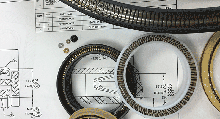
A spring-energized PTFE seal separates the sealing surface from the sealing force. The PTFE (or filled PTFE) jacket provides the low-friction contact surface; a precision metal spring seated inside it provides and maintains the contact force, independent of the polymer’s mechanical behavior. Because the spring carries the sustained load, it can deliver a nearly constant force across a wide deflection range and resist compression set almost entirely, which answers the 20-year question. The seal keeps compensating for jacket wear, misalignment, out-of-roundness, and eccentricity as they accumulate, rather than losing contact force as a plain PTFE lip does.

Three Spring Geometries, Three Different Jobs

Advanced EMC builds spring-energized seals with three spring geometries, each suited to different motion and friction requirements:

  • Cantilever (“V” or “M”) spring: offers a moderate load and deflection range, with a positive wiping action at the lip’s front edge. Well suited where the seal also needs to scrape out abrasive contamination off the shaft or race.
  • Canted coil (“W”/slant coil) spring, including Advanced EMC’s proprietary FlexForce design: provides a wide deflection range with a flat, relatively constant load curve, and correspondingly tight, predictable control of friction and torque. Wind industry literature points to this geometry specifically for pitch-drive gear seals. Each coil deflects independently, so canted coil springs also resist compression set well over long dwell periods.
  • Helical spring: offers a low deflection range and high unit load, and is used where the seal is essentially static or very slow-moving, and friction is not the limiting factor.
Spring Energized Teflon Seals

Matching Spring Geometry to Pitch vs. Yaw Duty

Pitch bearings oscillate slowly through a limited arc, reverse direction often, and sit through long dwell periods. Every bit of lip drag shows up as torque the pitch motor and gearbox must overcome, so friction predictability matters most. A canted coil spring is generally the better fit because its flat load curve keeps friction stable through dwell and reversal cycles, rather than relying on the PTFE’s own memory.

Yaw bearings rotate more continuously over a larger diameter, and onshore yaw seals often see more dust and grit than pitch seals buried in the hub. A cantilever spring, especially with a scraper-lip profile, often makes more sense here because the wiping action helps exclude contamination, and the slightly higher friction is easier to tolerate on a larger, more continuously rotating bearing.

The Spring Alloy Is Not an Afterthought

The spring geometry solves mechanical retention; the spring alloy solves corrosion and temperature exposure, and getting it wrong reintroduces the failure mode the spring was meant to eliminate. Stainless steel is the default for general-purpose duty. Hastelloy’s nickel-based chemistry is the step up for aggressively corrosive media. Elgiloy’s fatigue and corrosion resistance suit combined heat and salt-laden exposure, which is a real consideration offshore. Advanced EMC offers all three, plus other high-performance alloys, for FlexForce springs.

The Honest Tradeoffs

A spring energizer is not a free upgrade. It adds design variables, namely geometry and alloy, that must both be specified and qualified correctly. The gland or housing must be sized for the spring’s working deflection range, so a spring-energized seal generally is not a drop-in replacement for a housing designed around a standard lip seal. And it does not solve which PTFE compound should sit at the jacket face contacting grease and the shaft or race for two decades. That is a separate material question, covered in our companion article on jacket material selection.

Talk to a Sealing Engineer

If you are specifying seals for pitch or yaw bearings and need 20-year performance without a rising friction penalty on the pitch motor, Advanced EMC can help with spring geometry and alloy selection for your duty cycle. Contact us today to talk through FlexForce canted coil spring options with a sealing solutions engineer.
by Daniel Mays Daniel Mays No Comments

The PTFE Spring-Energized Seal as a Casualty: Why Hardware and Installation Are the Real Killers

A seal rarely fails in isolation, but this is often forgotten.  When leakage occurs, the immediate reaction is often to blame the seal itself. However, this approach frequently addresses the symptom rather than the disease. In many failure analyses, the seal is the casualty of a compromised environment. 

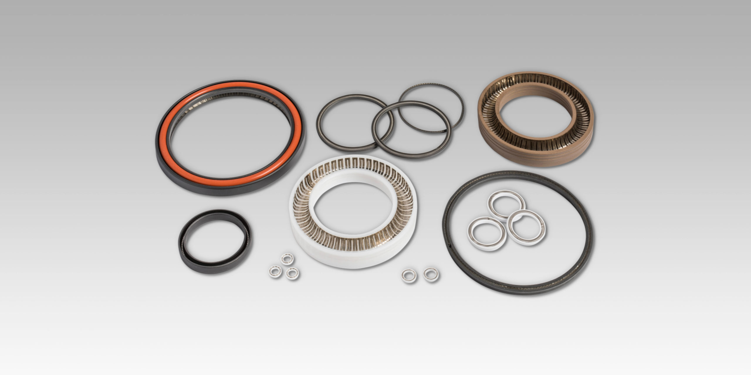
High-performance spring-energized seals do not function in an environment by themselves. Rather, they are dynamic elements within a complex mechanical system that continuously react to issues in hardware, surface finish, alignment, pressure, and thermal cycling. When these boundary conditions drift outside their engineering limits, even the most advanced spring-energized seal will inevitably fail.

To achieve genuine reliability, the conversation must shift from “seal failure” to “system integrity.”

The Tribological System

A spring-energized seal is more than a polymer ring with a metallic energizer: it is a critical component of a tribological system. As such, its performance can be directly linked to three factors:

  • Gland Design: Dimensions, geometric tolerances, and extrusion gaps
  • Counterface: Material hardness, coating integrity, and surface finish
  • Operational Physics: Thermal expansion coefficients (CTE), pressure-induced hardware deflection, and friction-generated heat

Each factor impacts the contact stress profile and wear mechanics, which means if one element is ignored, the seal attempts to compensate until the application’s physics overwhelm it.

Gland Geometry for Spring-Energized Seals

The gland design sets the boundary conditions for the spring-energized seal’s life.

Radial Squeeze & Contact Stress: A lack of compression can lead to the formation of spiral leakage pathways in dynamic applications, while excessive interference generates frictional heat and accelerates natural abrasive wear. For spring-energized designs, the incorrect squeeze distorts the energizer’s force-deflection curve, essentially voiding the design that went into the spring.

Groove Volumetrics: A groove that is too wide allows axial shuttling, where the shaft and seal move axially. This leads to a tilted seal and skewed loading profiles. In addition, a groove that violates fill percentage guidelines restricts thermal expansion, causing stress spikes.

Extrusion Gap Mechanics: Under high pressure, PTFE will exhibit cold flow behavior (which is a material property, not a defect). If the extrusion gap (E-gap) is excessive or expands due to hardware pressure breathing, the polymer will extrude into the clearance. In addition, hardware features like lead-in chamfers are critical. A sharp corner acts as a cutting tool during installation, shaving the seal before it ever sees service pressure.

Surface Finish: The Micro-Interface

Surface finish is far too often the silent killer in dynamic applications. It is not enough to specify smooth, but rather define the correct surface finish required for effective film transfer when using materials such as PTFE or PEEK. Keep in mind that PTFE seals rely on the deposition of a thin transfer film onto the mating hardware to stabilize friction. If the counterface is too rough, it abrades the seal lip. On the other hand, if the surface is a mirror polish, it will prevent lubricant retention or film adhesion, leading to serious issues related to high stick-slip friction. The shaft hardness must also support the load: a soft shaft can suffer from galling or scoring, while a delaminating coating means a jagged, abrasive interface that destroys the seal lip.

Thermal and Mechanical Instability

Polymers and metals behave differently thermally. For example, PTFE is going to expand significantly more than steel given the same temperature differential. If such a CTE mismatch is ignored, rising temperatures can cause the seal to overfill the gland, resulting in higher friction and torque. However, when the PTFE spring-energized seal is subject to cryogenic temperature, it may shrink away from the bore and lose contact stress unless the spring energizer is correctly sized to compensate for this dimensional change.

Mechanically, pressure is not static. Housings breathe, bores distort, and bolts stretch. In cyclic applications, the extrusion gap is a dynamic variable that opens and closes with every pressure spike. This forces the seal to fatigue as it continuously reshapes itself to bridge the changing gap.

Misalignment and Eccentricity

Runout and misalignment are simply unavoidable with a rotary shaft seal for several reasons. Eccentric forces on one side of the seal lead to high compression, while the opposite side of the seal lifts off, losing critical contact. This, in turn, results in localized wear patterns and half-moon extrusion failures. Often, the seal is expected to mask bearing slop or structural deflection, which is actually a band-aid for mechanical instability that should have been resolved at the design stage.

Installation of Spring-Energized Seals

Many seals are destroyed before the machine is even turned on. Installation is a violent event for a simple polymer ring. Forcing a seal to go over threads, sharp shoulders, or through undersized bores can slice the polymer jacket or permanently deform the spring energizer, neither of which is good. Installation can destroy a seal before it has had a chance to perform.

Conclusion

Leakage is not solely a material failure. This thought process ignores the complex interplay of gland geometry, surface finish, and thermal dynamics that dictate performance. Trueseal solution reliability requires moving beyond component replacement and embracing a holistic approach to system integrity.

At Advanced EMC, we engineer tribological solutions. If you need help navigating complex boundary conditions or recurring failures with your PTFE spring-energized seals, let our engineers help you analyze the total application. Contact us today to design a sealing system built for your specific operational situation.