Advanced EMC Technologies: Revolutionizing Sealing Solutions Across Industries
Advanced EMC Technologies is synonymous with innovation and excellence in PTFE sealing solutions. Our products are designed to meet the most demanding requirements across various industries. In this blog, we delve into real-world application examples to showcase the exceptional capabilities of our PTFE rotary shaft seals in diverse fields such as oil and gas, renewable energy, aerospace, and space exploration.
Real-World Application: PTFE Rotary Shaft Seals in Oil and Gas Drilling
Challenge: In the oil and gas industry, drilling operations face extreme conditions, including high pressures, temperatures, and exposure to harsh chemicals and abrasive materials. Traditional seals often fail under these conditions, leading to costly downtime and repairs.
Solution: Advanced EMC Technologies’ PTFE rotary shaft seals provide a reliable solution for these challenging environments. Let’s explore how our seals excel in this application:

High-Pressure Resistance: During drilling operations, equipment such as mud pumps and rotary steerable systems experience high pressures. Our PTFE seals can withstand pressures up to 15 bar, ensuring continuous operation without seal failure.
TYPES OF SEALS FOR OIL AND GAS INDUSTRY
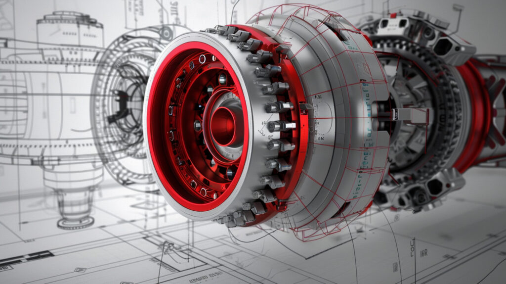
Broad Temperature Range: The temperature range in drilling operations can vary significantly, from sub-zero temperatures in deep-sea environments to high temperatures encountered during drilling. Our seals operate efficiently from -40 to +220°C, providing unmatched reliability.
THE BENEFITS OF PTFE SPRING ENERGIZED SEALS FOR OIL AND GAS

Chemical Resistance: Drilling fluids and chemicals used in oil and gas operations can be highly corrosive. Our PTFE seals offer exceptional resistance to a wide range of chemicals, preventing degradation and ensuring long-lasting performance.
HOW TO DESIGN AND SELECT SEALS FOR OIL AND GAS

Minimal Friction and Wear: Equipment downtime due to seal failure can be costly. Our PTFE rotary shaft seals are designed with a durable sealing lip that exhibits minimal friction and wear, reducing maintenance frequency and extending the life of the equipment.
THE OIL AND GAS INDUSTRY DURING COVID-19
Impact: By using our PTFE rotary shaft seals, oil and gas companies can achieve higher operational efficiency. The seals’ ability to withstand extreme conditions reduces the risk of equipment failure, ensuring continuous drilling operations and translating into significant cost savings.
Enhancing Energy Efficiency: PTFE Seals in Renewable Energy
Challenge: The renewable energy sector, including wind and solar power, demands reliable sealing solutions that can withstand environmental extremes and ensure efficient operation. Components must handle wide temperature ranges, exposure to elements, and continuous motion.
Solution: Advanced EMC Technologies’ PTFE seals are ideal for renewable energy applications. Here’s how:

Weather Resistance: Our seals provide excellent resistance to UV exposure, moisture, and extreme temperatures, making them perfect for outdoor applications such as wind turbine blades and solar panel mounts.
BENEFITS OF SPRING-ENERGIZED SEALS FOR WIND TURBINES

Durability: The high wear resistance of our PTFE seals ensures longevity, reducing the need for frequent maintenance and replacements in renewable energy installations.
WHEN TO USE A PTFE ROTARY SHAFT SEAL

Efficiency: By minimizing friction and wear, our seals contribute to the overall efficiency of energy generation systems, ensuring optimal performance and reduced energy loss.
SPRING-ENERGIZED SEALS FOR THE WIND INDUSTRY
Impact: Wind turbines and solar panels equipped with our PTFE seals perform more efficiently and require less maintenance, leading to lower operational costs and more sustainable energy production.
Taking Flight: PTFE Seals in Aerospace
Challenge: Aerospace applications demand sealing solutions that can endure high altitudes, temperature fluctuations, and extreme pressure conditions. Aircraft components require seals that guarantee safety and reliability.
Solution: Advanced EMC Technologies’ PTFE seals are designed to meet these stringent requirements. Here’s why our seals are a top choice for aerospace:

Temperature Tolerance: Our seals perform effectively across a broad temperature range, from the cold of high altitudes to the heat generated by aircraft engines.
A COMPREHENSIVE GUIDE TO AEROSPACE SEALS

Pressure Resistance: The high-pressure resistance of our PTFE seals ensures reliability in hydraulic systems, fuel systems, and other critical components.
SPRING-ENERGIZED SEALS FOR SPACEFLIGHT

Lightweight: Weight is a critical factor in aerospace applications. Our PTFE seals are lightweight yet robust, contributing to overall aircraft efficiency without compromising on performance.
Impact: Our seals ensure that aircraft components operate smoothly and safely, reducing the risk of mechanical failures and enhancing the overall reliability and efficiency of aerospace systems.
Reaching for the Stars: PTFE Seals in Space Exploration
Challenge: Space missions involve extreme conditions, including vacuum, radiation, and cryogenic temperatures. Seals used in rockets and spacecraft must offer exceptional reliability and durability to ensure mission success.
Solution: Advanced EMC Technologies’ PTFE seals are perfect for space applications. Here’s how they make a difference:
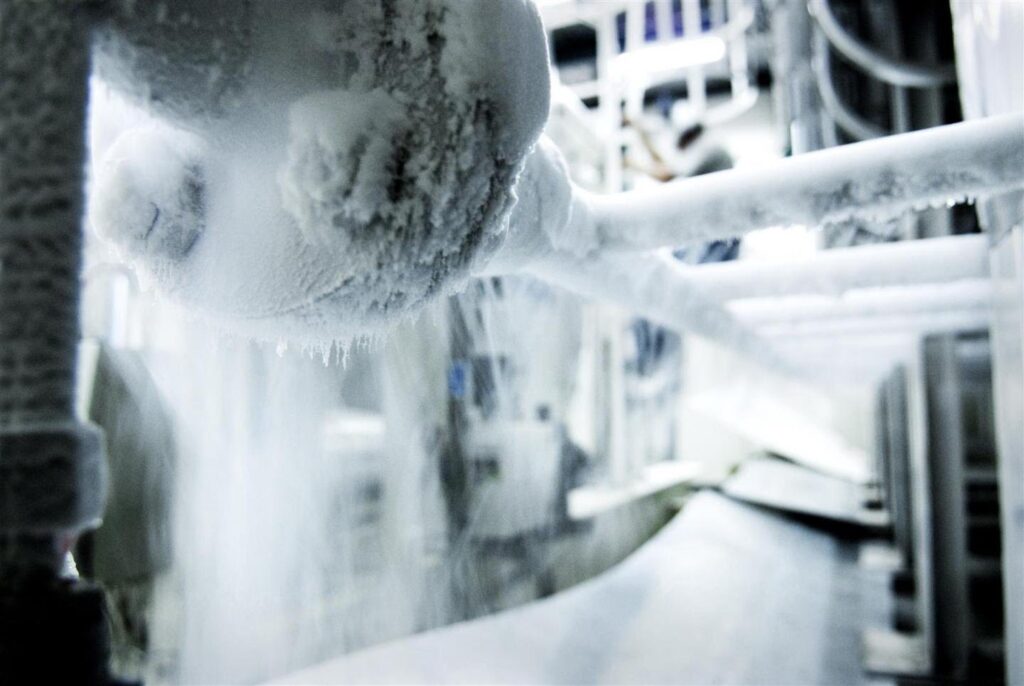
Cryogenic Performance: Our seals maintain integrity at cryogenic temperatures, crucial for handling rocket fuels like liquid oxygen (LOX) and liquid hydrogen.
SEALS IN SPACE: THE UNSUNG HEROES OF ROCKETRY

Vacuum Compatibility: PTFE’s properties make our seals ideal for use in the vacuum of space, where traditional materials might fail.
A COMPREHENSIVE GUIDE TO AEROSPACE SEALS

Chemical Inertness: The chemical resistance of our PTFE seals ensures they can withstand exposure to various rocket propellants and other harsh substances used in space missions.
Impact: Our seals play a vital role in the success of space missions by ensuring the reliability and safety of critical components, from rocket engines to spacecraft systems.

Why Choose Advanced EMC Technologies?
- Customization: We understand that each application has unique requirements. Our team works closely with clients to design and manufacture customized PTFE seals that meet specific operational needs.
- Quality Assurance: Our seals are manufactured to the highest standards, ensuring consistent quality and performance. We utilize advanced materials and manufacturing processes to deliver superior products.
- Expert Support: From initial consultation to after-sales support, our team of experts is dedicated to providing exceptional service. We assist clients in selecting the right seals and offer ongoing support to ensure optimal performance.
Advanced EMC Technologies‘ PTFE rotary shaft seals are transforming industries by providing reliable, high-performance sealing solutions. Our seals are engineered to excel in the most challenging environments, ensuring operational efficiency, cost savings, and environmental safety.
Whether it’s drilling deep in the earth, harnessing the power of the wind and sun, soaring through the skies, or exploring the final frontier, Advanced EMC Technologies has the sealing solutions to keep your operations running smoothly.
For more information about our products and services, visit our website or contact our sales team at Sales@advanced-emc.com. Let Advanced EMC Technologies be your trusted partner in sealing solutions for all your industrial needs.



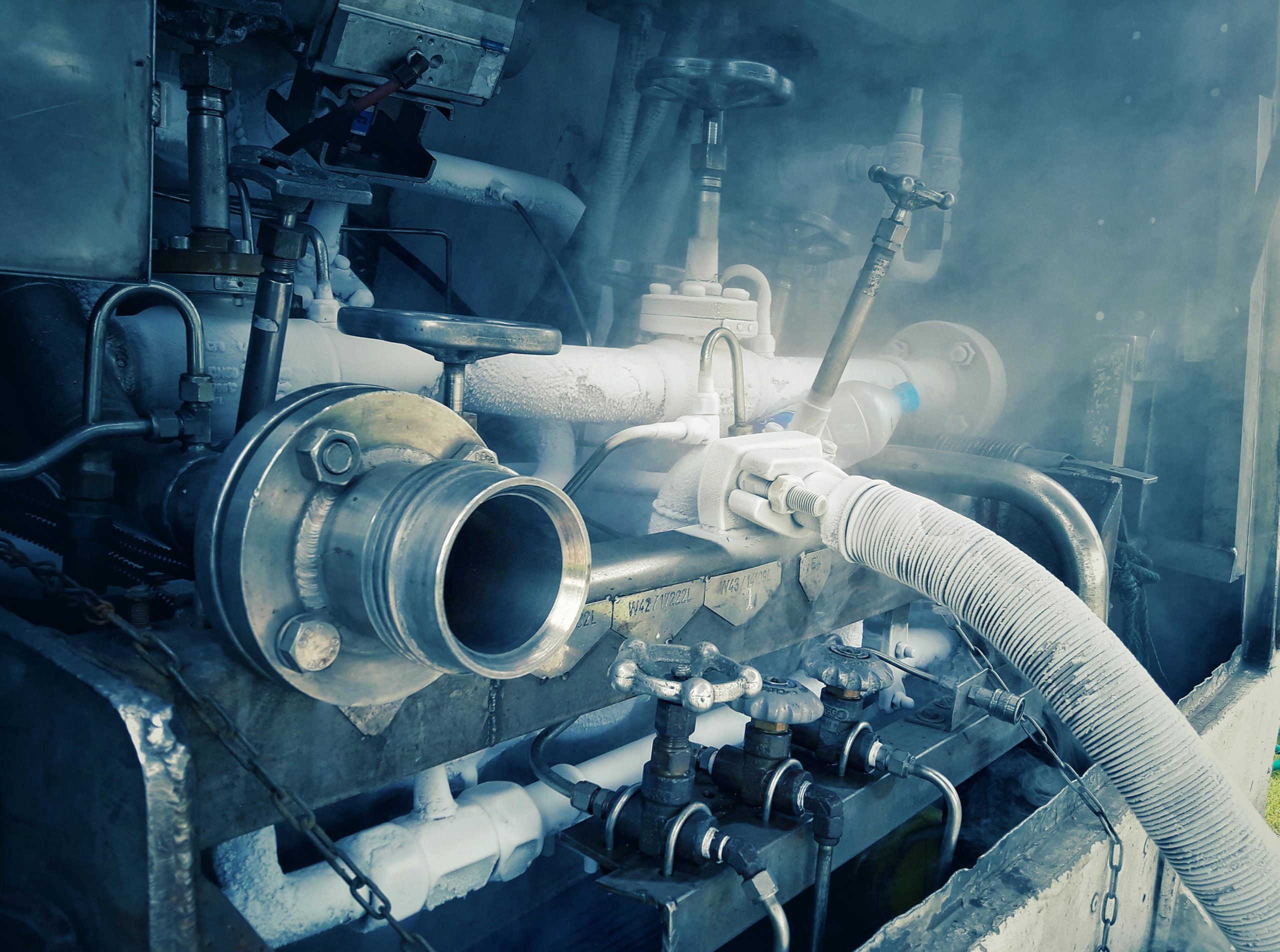
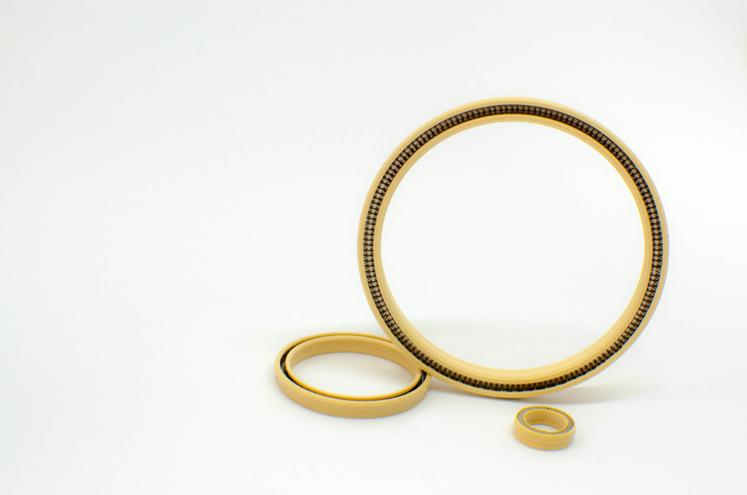
 Leaks involving LNG (Liquified Natural Gas) at cryogenic temperatures are dangerous to the health and safety of workers and to plant operation. Issues such as toxicity, extreme cold, asphyxiation, flammability, and explosions resulting from rapid expansion of LNG all point to the need for a reliable, leak-proof seal.