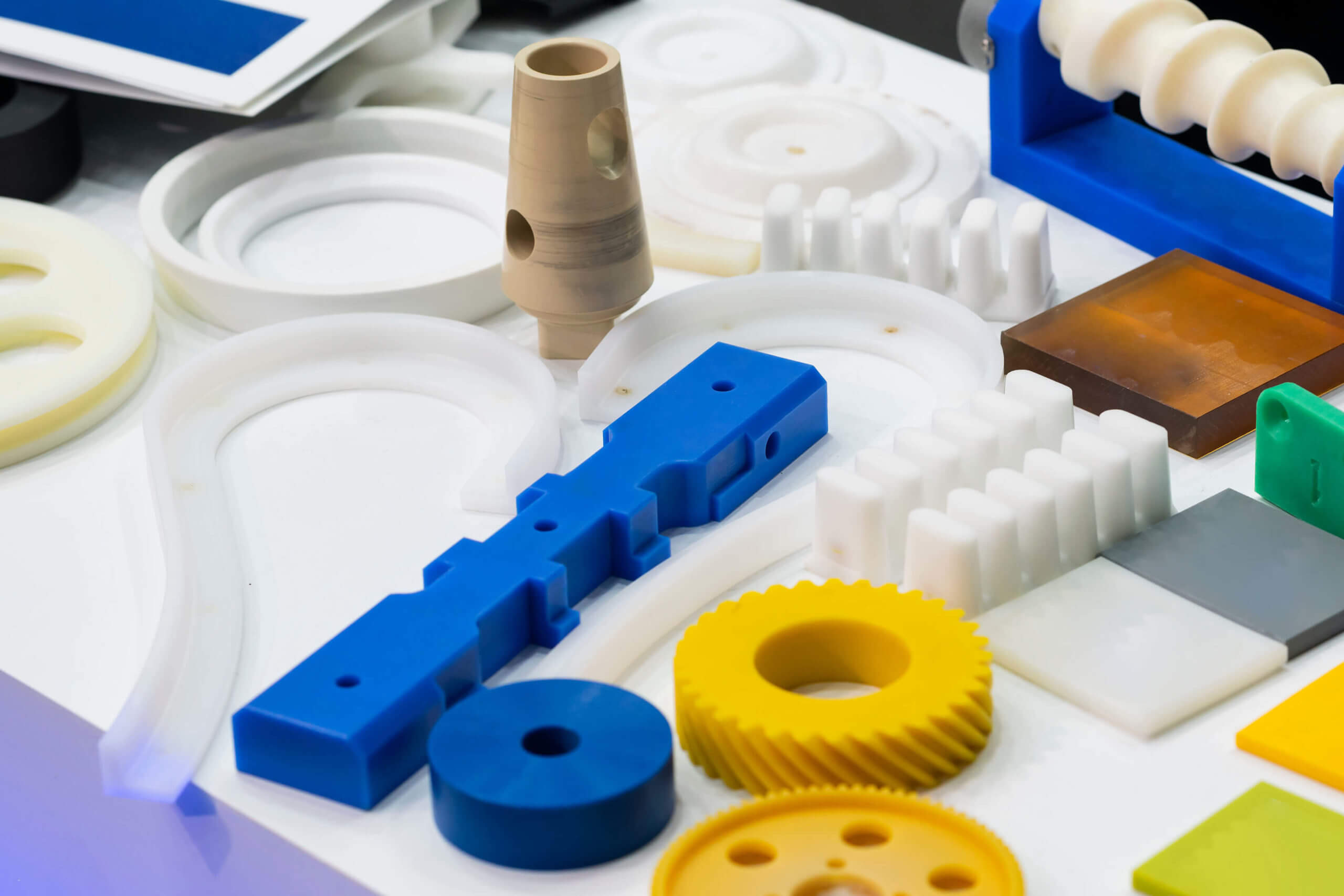
Injection molding vs. precision machining: Which process is best for manufacturing polymer components? Each one offers its own distinct advantages that depend on factors such as part geometry, material type, production volume, and performance requirements.
In this blog post, we compare both methods to help you determine the most suitable solution for your project.
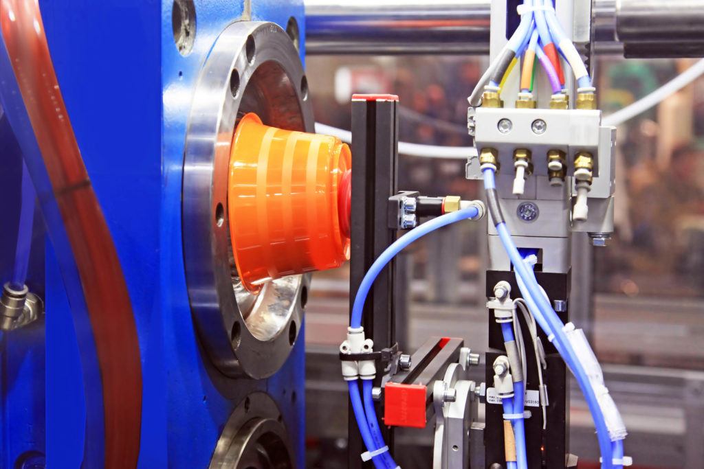
Injection Molding
Injection molding is a high-throughput manufacturing process in which molten plastic is injected into a closed mold under high pressure. The mold defines the final shape of the part, and after cooling, the component is ejected. This method is widely used for thermoplastics and is especially effective for large production runs of identical parts.
Pros
There are several key advantages to injection molding, starting with its scalability and cost efficiency. For example, once tooling is completed, per-unit costs drop significantly. This makes it ideal for high-volume production (typically 5,000 to 10,000+ parts). Cycle times are also fast, usually ranging from 15 to 120 seconds, and because these processes are highly automated, they have reduced labor requirements and overhead.
Injection molding also produces highly uniform parts with tight tolerances (up to ±0.005″) and excellent surface finish, supporting intricate geometries and undercuts that may be impractical to machine. They are also highly material efficient and support the recycling of sprues and runners.
In addition, injection molding is compatible with a wide range of thermoplastics, including fluoropolymers such as PTFE and PEEK.
Cons
There are some drawbacks to injection molding, as well. There can be high initial tooling costs and a longer lead time because mold design and fabrication both require significant investments of money and time (possibly adding weeks to the project timeline). In addition, parts may be subject to design constraints such as uniform wall thickness and draft angles.
Some polymers may be more difficult to injection mold because of issues with melt behavior, and there may be high melt temperatures may lead to more complexity. Also, parts may require post-molding annealing to reduce warping and internal stresses.
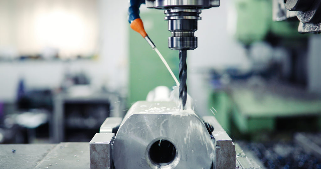
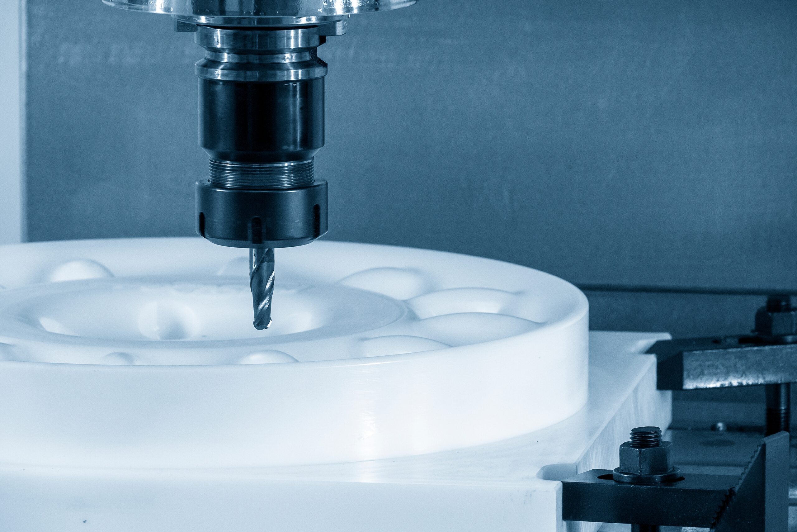
Precision Machining
Precision machining is a subtractive process that removes material from solid stock to achieve final dimensions. It is particularly suited for high-performance polymers and applications requiring tight tolerances or low production volumes.
Pros
There are significant benefits to using precision machining to manufacture polymer components. For example, it is ideal for prototyping and cost-effective for small runs under 5,000 parts and does not require molds or extensive tooling. And because precision machining does not require mold design and fabrication, it eliminates the significant delays associated with injection molding.
Precision machining is capable of ultra-tight tolerances, often better than ±0.001″, and results in superior part integrity because of the lack of ‘residual flash’. Residual flash is the excess material that can be left around the parting line in injection molding, which needs to be removed. In addition, machined parts retain the full mechanical, thermal, and chemical properties of high-performance polymers. It can also handle features like threads, deep bores, and undercuts.
Cons
Because machining is a material removal process, there may be much higher waste compared to net-shape processes like injection molding. Machining also becomes less cost-effective as the production volume increases. It also requires specialized knowledge to achieve optimal results with advanced polymers.
Which One Should I Use: Injection Molding vs. Precision Machining
The decision between injection molding vs. precision machining should be based on production volume, material selection, tolerance requirements, design complexity, budget, and lead time. Below is a table that summarizes those factors.
| Factor | Injection Molding | Precision Machining |
| Production Volume | Best for high-volume production (5,000–10,000+ parts) | Ideal for low-volume runs and prototyping |
| Material Selection | Suitable for many thermoplastics; some fluoropolymers are challenging to process | Better suited for difficult-to-mold polymers or specialty high-performance materials |
| Tolerance Requirements | Good dimensional consistency, but limited by mold shrinkage | Preferred for ultra-precise, tight-tolerance components |
| Design Complexity | Excellent for producing intricate shapes and fine details within mold limitations | More flexible for unconventional geometries and non-uniform features |
| Budget & Lead Time | High upfront tooling costs; longer lead times for setup | Lower initial cost; faster turnaround for small batches |
Conclusion
For high production volumes with a low per-unit cost, injection molding is usually recommended,especially when part geometry is compatible with mold design. Precision machining, on the other hand, excels in delivering complex, high-performance components in low volumes, where material properties, tight tolerances, or custom features are critical.
Here at Advanced EMC Technologies, our team specializes in both injection molding and precision machining for high-performance polymer components. Whether you need thousands of parts or a single precision prototype, our engineering team is ready to help you choose the optimal manufacturing process. Contact us today to discuss your project requirements.