by Sara McCaslin, PhD Sara McCaslin, PhD No Comments

How Spring Selection Defines Spring-Energized Seal Performance

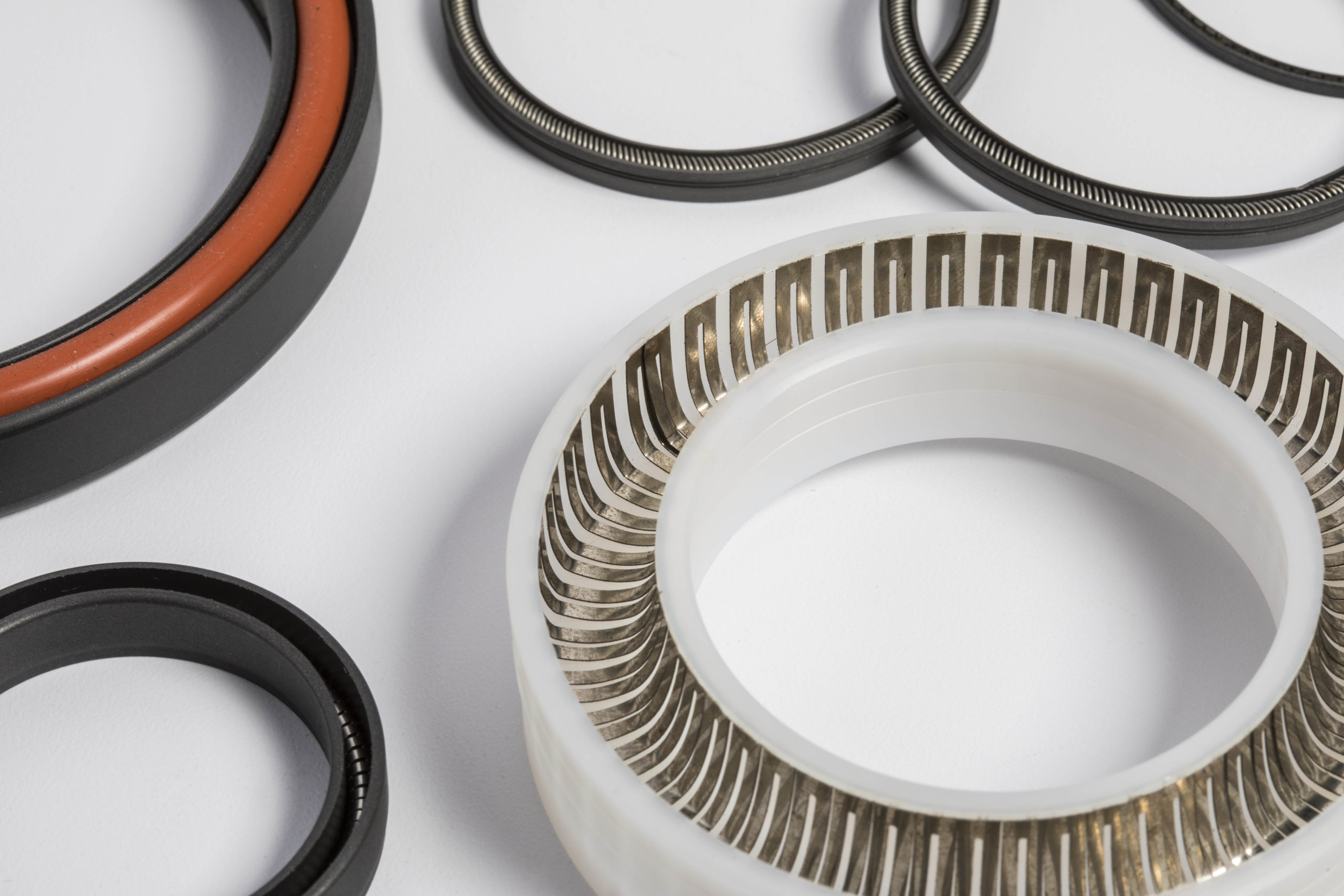
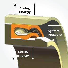
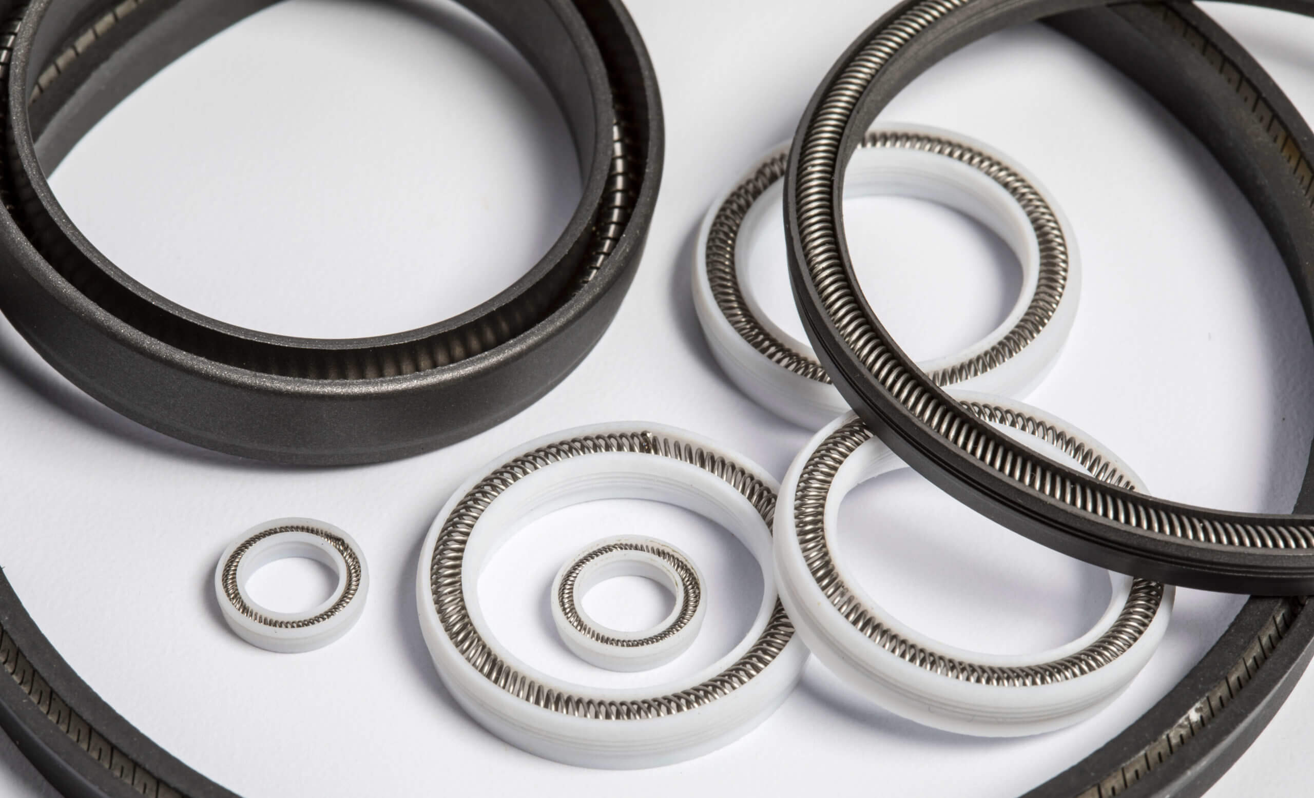
Most failures blamed on PTFE actually originate in the spring. This blog post discusses the load-management system and key features of spring-energized seals for canted coil springs, V springs, cantilever springs, helical springs, and coil springs.

Canted Coil Springs (Slant Coil Springs)

Canted Coil Springs and Slant Coil Springs from Advanced EMC Technologies

These springs are wound so that individual coils are set at an angle to the longitudinal axis. They are highly versatile and often used for dynamic sealing applications. Their key feature of canted coil springs is the flat load curve they provide. These spring energizers generate a nearly constant force across a wide deflection range. The constant force allows precise control over friction and torque, making these spring energizers ideal for applications where these factors are critical. Canted coil springs are also unlikely to experience compression set.

Canted coil spring energizers work best in moderate to high-speed rotary applications. Beyond sealing, their unique design allows them to serve as mechanical connectors (latching/locking), EMI/RF shields, and multi-point electrical conductors.

V Springs (V Ribbon Springs)

The V spring is a general-purpose, cantilever-type energizer. They offer an excellent balance of performance and cost-effectiveness. In addition, V springs provide a moderate load over a wide deflection range. They function well in both static and dynamic applications, including those involving rotary or reciprocating motion.

V springs are frequently recommended for severe service conditions, including vacuum pressures and cryogenic temperatures. V spring energizers are often a preferred choice for harsh operating environments.

Cantilever Springs (Finger Springs)

Often referred to as finger springs, these spring energizers feature a V-shaped cross-section and are distinguished by a linear load curve, meaning the force increases linearly with deflection.

The load is concentrated at the very front edge of the seal lip, which provides positive wiping action and makes them particularly effective for exclusion and scraping applications. They also generate extremely low friction.

Cantilever spring energizers are well-suited for sealing viscous media. They are typically found in low to medium-speed applications, such as hydraulic cylinders, pumps, compressors, and shocks.

Helical Springs (Helical Flat / Compression Springs)

Helical springs consist of a wound ribbon of metal and are characterized by a high load-versus-displacement curve. Because they produce a very high unit load with a small deflection range, helical springs provide tight, reliable sealing. They are well-adapted for sealing light gases and liquids.

Helical springs are generally limited to static, slow-dynamic, or intermittently dynamic applications because friction and wear are less of a concern than seal reliability. These spring energizers are often used in pipe flanges and crush jackets where the seal must embed into surface irregularities. Experts highly recommend helical configurations for cryogenic applications.

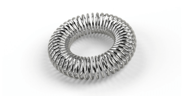
Coil Springs (Spiral Pitch Springs)

When many people visualize a spring-energized seal, they picture this wire coil type. These spring-energizers actually perform best in high-pressure, medium-speed applications and are known for their low friction. 

Spring Materials

The performance of spring-energizers is also dependent on the material selection. The material selection is primarily determined by the chemical and thermal environments involved. At Advanced EMC, we recommend one of the following spring materials: 

  • Stainless Steel (300 Series, 17-7 PH, 301/304): Common for general-purpose and cryogenic applications
  • Hastelloy: Recommended for highly corrosive media
  • Elgiloy: Used for high heat, corrosive environments, and salt water
  • Inconel: Used in severe environments and cryogenic applications

Conclusion

When spring-energized seals fail, the problem is often not the jacket, but the spring. Knowing about load consistency, deflection behavior, and how that force is delivered over time is key to deflection, friction, wear, and whether a seal actually survives its operating environment.

At Advanced EMC, spring-energized seals are engineered as complete systems, not just components. Our team will assist you from spring selection to geometry and material pairing, aligning the seal design with real-world conditions. If you are troubleshooting a failure or designing for demanding service, contact Advanced EMC today.

by Sara McCaslin, PhD Sara McCaslin, PhD No Comments

Seal Gland Design for Spring-Energized PTFE Seals

Seal gland design is an important aspect of effective spring-energized PTFE seals and is also the source of most leaks. Such seals can only perform as well as the seal gland supporting them, and even a small geometry error can lead to issues with extrusion, rapid wear, low contact stress, and spiral leakage.

This blog post reviews what makes PTFE spring-energized seals different from other sealing solutions, and then discusses key aspects of gland design, including the anatomy of a basic spring-energized seal and design aspects of geometry and surface finish that have the greatest impact on seal reliability. 

Anatomy of a Spring-Energized Seal

A short review of spring-energized seals is in order. 

The gland is the machined groove in the metal hardware where the seal sits. In the diagram, you can see the E-gap, or extrusion gap. This is a small clearing between the moving and stationary metal parts of the seal. This gap must be kept tight to prevent the seal from extruding or flowing into it under pressure.

The seal jacket is the U-shaped outer body, which, in PTFE spring-energized seals, is manufactured from PTFE. It provides the main sealing interface against the hardware, and the lips of the jack are the points that actually touch the mating surface.

The spring energizer is contained within the jacket, and it provides constant pressure against the jacket lips and provides pressure outward against the gland walls. This pressure, or sealing force, is maintained by the spring-energizer within the jacket and exists even when there is low to no system pressure. As system pressure increases, the jacket enters the U-cup and further augments the spring’s force and the sealing force.

Practical Seal Gland Design Geometry

PTFE is not flexible like elastomers, and that must be taken into account when specifying the gland geometry. First, proper gland width provides the seal with enough clearance to float, and the gland depth strictly controls the interference, and both are critical for providing sufficient axial and radial freedom instead of just simply squeezing the seal into place. 

When the design creates over-compression, the seal will not be able to flex as it should. This leads to increased friction, accelerated jacket wear, and a potential locked condition where the spring cannot compensate for shaft misalignment. Under-compression brings its own set of problems because it will not be able to fully utilize the spring energy. Leakage at low pressures and a delayed response during pressure spikes severely impact the performance of the seal. 

The goal with the design then becomes the achievement of a uniform load distribution that can conform to surface irregularities and maintain the integrity of the seal.

Seal Gland Design: Corner Radii and Lead-In Geometry

PTFE is softer than steel. If you try to shove this plastic seal into a metal bore that has a sharp 90° corner, that corner acts like a knife. It will slice a layer off your seal before the machine even turns on. This can lead to micro-damage that will later present itself as problematic leaks.

Sharp edges are one of the main causes of damage during PTFE seal installation, and this differs significantly from elastomeric seals. PTFE is stiffer, which makes it more likely to suffer a cut from insertion into a metal bore at a 90° angle. The solution is a shallow lead-in chamfer or on-ramp that is around 15° to 20°, and longer than the seal itself. The length is necessary to ensure the seal is fully compressed before it enters the main bore. In addition, the ramp corners must be rounded, and no sharp edges are allowed.

Seal Gland Design: Surface Finish and Hardware Interaction

Because these seals are constantly rubbing against metal, the surface finish of the metal is of utmost importance. If the surface is too rough, it will abrade the seal and lead directly to leakage. On the other hand, if the surface is too smooth (e.g., mirror polish), it will not be able to hold, and the seal will wipe the sealing surface dry. In addition, because PTFE is self-lubricating and forms a transfer film on the sealing surface, the surface cannot be so smooth that the transfer film does not stick. 2 RMS to 16 RMS, depending on what your application is. 

For gases and liquids at cryogenic temperatures, you want a smoother finish with an RMS between 2 and 4. For gases at non-cryogenic temperatures, the recommended surface finish is between 6 and 12 RMS. For liquids, a surface finish between 8 and 16 RMS is sufficient.

In addition, it is important to specify a plunge-ground finish (0° lead) to prevent spiral tool marks from acting as a screw pump that leaks fluid regardless of seal tightness. 

Seal Gland Design: Squeeze, Clearance, and Extrusion Gap Control

Under extremely high pressures, the behavior of PTFE is significantly different from that of elastomers. At extremely high pressures, PTFE is more likely to flow like a liquid to an area of lower pressure. There will always be a small gap between your piston and cylinder wall to prevent them from grinding against each other. This small gap is known as the extrusion gap, or E-gap. If the gap is too large, the pressure will push the heel of the seal into the gap, shredding the seal. This is where careful specifications come in: when specifying the diameter, include a small enough tolerance to ensure that the gap remains small (e.g., smaller than a human hair) even when the parts move.

Conclusion

Seal gland design for PTFE spring-energized seals is a little different from elastomeric seals and involves more focus on aspects such as geometry, lead-in geometry, surface finish, and extrusion gap control. 

If you need help with a PTFE spring-energized seal, our engineers at Advanced EMC are here and ready to help. Contact us today!