
by Daniel Mays Daniel Mays No Comments

Seal Gland Design for Spring-Energized PTFE Seals

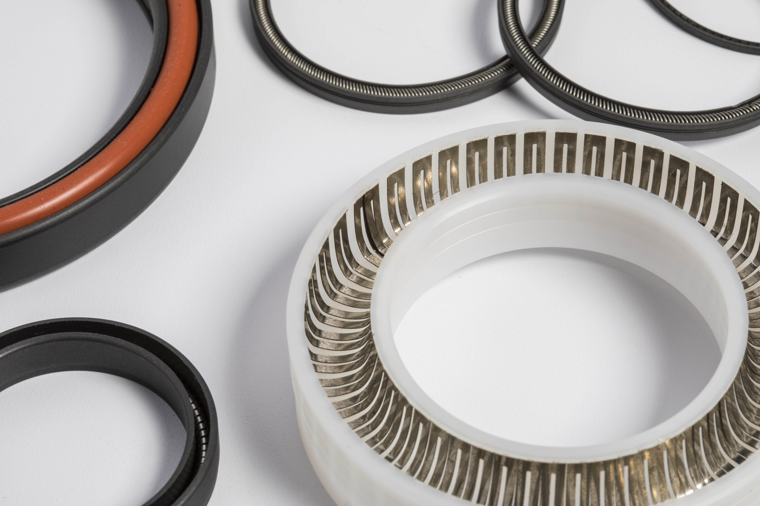
Seal gland design is an important aspect of effective spring-energized PTFE seals and is also the source of most leaks. Such seals can only perform as well as the seal gland supporting them, and even a small geometry error can lead to issues with extrusion, rapid wear, low contact stress, and spiral leakage.

This blog post reviews what makes PTFE spring-energized seals different from other sealing solutions, and then discusses key aspects of gland design, including the anatomy of a basic spring-energized seal and design aspects of geometry and surface finish that have the greatest impact on seal reliability. 

Anatomy of a Spring-Energized Seal

A short review of spring-energized seals is in order. 
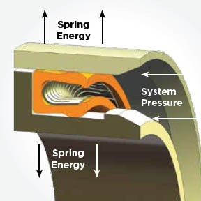
The gland is the machined groove in the metal hardware where the seal sits. In the diagram, you can see the E-gap, or extrusion gap. This is a small clearing between the moving and stationary metal parts of the seal. This gap must be kept tight to prevent the seal from extruding or flowing into it under pressure.

The seal jacket is the U-shaped outer body, which, in PTFE spring-energized seals, is manufactured from PTFE. It provides the main sealing interface against the hardware, and the lips of the jack are the points that actually touch the mating surface.

The spring energizer is contained within the jacket, and it provides constant pressure against the jacket lips and provides pressure outward against the gland walls. This pressure, or sealing force, is maintained by the spring-energizer within the jacket and exists even when there is low to no system pressure. As system pressure increases, the jacket enters the U-cup and further augments the spring’s force and the sealing force.

Practical Seal Gland Design Geometry

PTFE is not flexible like elastomers, and that must be taken into account when specifying the gland geometry. First, proper gland width provides the seal with enough clearance to float, and the gland depth strictly controls the interference, and both are critical for providing sufficient axial and radial freedom instead of just simply squeezing the seal into place. 

When the design creates over-compression, the seal will not be able to flex as it should. This leads to increased friction, accelerated jacket wear, and a potential locked condition where the spring cannot compensate for shaft misalignment. Under-compression brings its own set of problems because it will not be able to fully utilize the spring energy. Leakage at low pressures and a delayed response during pressure spikes severely impact the performance of the seal. 

The goal with the design then becomes the achievement of a uniform load distribution that can conform to surface irregularities and maintain the integrity of the seal.

Seal Gland Design: Corner Radii and Lead-In Geometry

PTFE is softer than steel. If you try to shove this plastic seal into a metal bore that has a sharp 90° corner, that corner acts like a knife. It will slice a layer off your seal before the machine even turns on. This can lead to micro-damage that will later present itself as problematic leaks.

Sharp edges are one of the main causes of damage during PTFE seal installation, and this differs significantly from elastomeric seals. PTFE is stiffer, which makes it more likely to suffer a cut from insertion into a metal bore at a 90° angle. The solution is a shallow lead-in chamfer or on-ramp that is around 15° to 20°, and longer than the seal itself. The length is necessary to ensure the seal is fully compressed before it enters the main bore. In addition, the ramp corners must be rounded, and no sharp edges are allowed.

Seal Gland Design: Surface Finish and Hardware Interaction

Because these seals are constantly rubbing against metal, the surface finish of the metal is of utmost importance. If the surface is too rough, it will abrade the seal and lead directly to leakage. On the other hand, if the surface is too smooth (e.g., mirror polish), it will not be able to hold, and the seal will wipe the sealing surface dry. In addition, because PTFE is self-lubricating and forms a transfer film on the sealing surface, the surface cannot be so smooth that the transfer film does not stick. 2 RMS to 16 RMS, depending on what your application is. 

For gases and liquids at cryogenic temperatures, you want a smoother finish with an RMS between 2 and 4. For gases at non-cryogenic temperatures, the recommended surface finish is between 6 and 12 RMS. For liquids, a surface finish between 8 and 16 RMS is sufficient.

In addition, it is important to specify a plunge-ground finish (0° lead) to prevent spiral tool marks from acting as a screw pump that leaks fluid regardless of seal tightness. 

Seal Gland Design: Squeeze, Clearance, and Extrusion Gap Control

Under extremely high pressures, the behavior of PTFE is significantly different from that of elastomers. At extremely high pressures, PTFE is more likely to flow like a liquid to an area of lower pressure. There will always be a small gap between your piston and cylinder wall to prevent them from grinding against each other. This small gap is known as the extrusion gap, or E-gap. If the gap is too large, the pressure will push the heel of the seal into the gap, shredding the seal. This is where careful specifications come in: when specifying the diameter, include a small enough tolerance to ensure that the gap remains small (e.g., smaller than a human hair) even when the parts move.

Conclusion

Seal gland design for PTFE spring-energized seals is a little different from elastomeric seals and involves more focus on aspects such as geometry, lead-in geometry, surface finish, and extrusion gap control. 

If you need help with a PTFE spring-energized seal, our engineers at Advanced EMC are here and ready to help. Contact us today!

by Daniel Mays Daniel Mays No Comments

Sealing the Depths: Spring-Energized PTFE Seals for HPHT Downhole Tools

Oilfield environments often require PTFE seals for HPHT (High-Pressure, High-Temperature) downhole tools. And this should come as no surprise, because oilfield environments represent some of the harshest sealing conditions on Earth. Temperatures can exceed 200°C and pressures can easily surpass 20 ksi. There will be exposure to media, including hydrocarbons, hydrogen sulfide (H₂S), CO₂, and amines, which can quickly render traditional sealing solutions ineffective. In such unforgiving conditions, even minor seal failure can trigger catastrophic leaks, equipment damage, or non-productive time (NPT) costing thousands of dollars per hour. That’s where spring-energized PTFE seals come into play: they are engineered precisely for high-pressure, high-temperature (HPHT) downhole environments where traditional materials fall short.

In this blog post, we’ll explore the use of spring-energized PTFE seals for HPHT applications, as well as material selection and design considerations, followed by an overview of their applications in the oil and gas industry.

Why Consider Spring-Energized PTFE Seals for HPHT Oil & Gas Environments

Unlike elastomeric seals, which tend to soften, swell, or degrade when subjected to harsh fluids and heat, spring-energized PTFE seals combine the advantages of fluoropolymer chemistry with the power of metal energizers. The result is a hybrid sealing solution that can maintain a consistent sealing force in the most demanding oil & gas applications. This solution is able to compensate for thermal expansion and resist creep under sustained load. In the depths of oil wells or even in subsea installations, this hybrid spring-energized PTFE sealing solution can make the difference between failure and flawless performance.

The HPHT Challenge: Pressure, Temperature, and Chemistry

The deeper a system operates, the more intense the pressure and temperature gradients become. Under extreme differential pressure, soft polymers tend to extrude into clearance gaps between mating surfaces, especially in dynamic or reciprocating applications. At the same time, thermal cycling in HPHT environments causes differential expansion between metal housings and polymer elements. These dimensional shifts alter contact pressure and can lead to intermittent leakage or total seal failure.

Chemistry further complicates the situation. Aggressive fluids such as drilling muds, completion brines, and sour gases attack the molecular structure of conventional elastomers like NBR or FKM. When combined with vibration, mechanical shock, and pressure fluctuations, these factors cause compression set, abrasion, and fatigue cracking. In essence, a seal in a downhole environment must perform under a complex blend of mechanical, chemical, and thermal stress—often simultaneously and continuously.

Why Spring-Energized PTFE Seals Excel in HPHT Conditions

Spring-energized PTFE seals are capable of solving some of the weaknesses that are inherent in traditional designs. The PTFE jacket provides a low-friction, chemically inert sealing interface, while the internal metallic energizer (often a canted coil, V-spring, or helical design) applies a consistent load across the sealing surface. This ensures reliable contact pressure even when temperature or system pressure fluctuates dramatically.

As well pressure increases, the system itself reinforces the seal: fluid pressure energizes the PTFE jacket, pushing it against the mating hardware for a tighter, more reliable seal even in the presence of wide-ranging pressure changes and across wide temperature ranges. Filled PTFE jackets, such as those reinforced with glass, graphite, or carbon, can also minimize cold flow and enhance wear resistance, further extending service life in dynamic applications.

Because PTFE’s coefficient of friction is among the lowest of any solid material, it minimizes heat generation and stick-slip behavior in reciprocating or rotating motion. This self-lubricating, no stick quality is particularly useful when used with directional drilling motors and measurement-while-drilling (MWD) systems, where frictional heating can distort readings or damage sensitive components.

Material Selection for Downhole Sealing

Material selection defines the performance window of a seal. Virgin PTFE offers excellent chemical resistance and thermal stability, but has its limitations. PTFE’s natural creep resistance under prolonged load can be limited; this issue can be addressed through the use of fillers such as carbon, bronze, or glass are incorporated to increase the elastic modulus and wear resistance. These filled PTFE formulations combine durability with the chemical inertness essential for downhole fluids.

The choice of spring material is also critical. Inconel 718 and Elgiloy are common due to their superior strength, fatigue life, and corrosion resistance in sour environments. These two alloys in particular maintain a highly stable spring force even after extensive compression cycles. They aid the PTFE spring-energized seal in ensuring consistent sealing load over long service intervals.

Design Considerations for Spring-Energized PTFE Seals for HPHT Downhole Applications

Precision in design directly impacts seal life. Hardware surface finish must be carefully controlled (Ra values below 8 µin are typical for dynamic sealing surfaces) to prevent wear and micro-leakage. Extrusion gaps must be minimized, particularly when pressure exceeds 15 ksi. Where necessary, designers incorporate anti-extrusion rings or step-cut backup rings to maintain stability.

Thermal expansion is another major design consideration for downhole applications. PTFE expands significantly more than steel when heated, which can affect gland squeeze and frictional characteristics. Engineers must calculate clearances and tolerances to account for this mismatch.

Seal geometry also matters. Single-lip designs are suitable for rotary applications, while double-lip or pressure-balanced configurations are preferred in static or reciprocating systems to prevent fluid entrapment. Venting pathways behind seals may also be required to prevent trapped pressure differentials, which can cause extrusion or blowout during depressurization cycles.

Applications Across Oil and Gas Systems

Spring-energized PTFE seals have proven themselves across a wide range of oil and gas applications. In MWD (Measurement While Drilling) and LWD (Logging While Drilling)  systems, they protect internal electronics from drilling mud and hydrocarbon ingress while enduring continuous vibration and pressure pulsing. In completion tools, packers, and valves, these seals maintain long-term reliability under chemical attack and mechanical load.

Subsea valves, connectors, and actuators rely on spring-energized PRFE seals for high-pressure, high-temperature applications in oil & gas to maintain zero leakage across temperature extremes and under deep-water hydrostatic pressure. High-pressure pumps and reciprocating actuators use these seals to minimize downtime, extend maintenance intervals, and maintain consistent performance across thousands of operational cycles.

Performance that Endures Where Elastomers Fail

In HPHT downhole service, traditional elastomer seals simply can’t cope with the combined assault of heat, pressure, and chemistry. Spring-energized PTFE seals for high-pressure, high-temperature applicants bridge the gap between flexibility and endurance, offering predictable performance where failure is not an option. Their combination of low friction, corrosion resistance, and mechanical adaptability makes them indispensable in modern oilfield equipment.

As operators push deeper into the earth’s crust and toward higher-pressure, higher-temperature reserves, the demand for advanced sealing materials will continue to rise. Spring-energized PTFE seals—especially those engineered with filled PTFE and high-performance alloys—represent the next generation of reliability in extreme sealing applications.

If you are looking for a reliable sealing solution for HPHT download tools, contact Advanced EMC today. Our engineering team is ready to work with you to extend equipment life, enhance safety, and maintain uptime in some of the world’s most demanding operating environments.