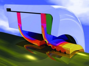
Another key aspect of developing a finite element model of a seal is the generating the mesh.
The mesh has a tremendous effect on the accuracy of solution. In this blog post, we will discuss mesh generation, discretization error, and some common methods of mesh refinement.
What Is a Mesh?
When you see the results of a finite element analysis, you might notice what looks like a grid superimposed on the parts. This grid shows how the components were divided into elements and represents the mesh that was used to achieve a solution.
The mesh lies at the very heart of a finite element model. Essentially, it is the process of dividing the geometric model of the components represented (seal lip, seal case, etc.) into a finite number of elements. Keep in mind that a solution to a finite element model is obtained by applying the basic laws of physics to each element in mesh.
Generating the Mesh
The mesh is generated by the computer, either by the finite element software package you are using or by another package that specializes in meshing. When the software package stores the information for the mesh, it assigns a unique number to each element in the model. Each element has nodes — a minimum of one node at each corner. The geometric coordinates for the nodes are stored, and are used to define the mesh. There is quite a bit that goes on under the hood when it comes to keeping track of elements and nodes, but that would be a topic for another post. Suffice it to say that when a mesh is generated, enough information is stored about each node to define its location in the model and to establish the correct relationships between neighboring elements.
Discretization Error
When you take a continuous object like the lip of a seal and model it using a finite number of individual elements, you will introduce error into your results. This type of error is called discretization error and is unavoidable. The more elements you use, resulting in a finer mesh, the smaller the discretization error will be; on the other hand, a coarse mesh with fewer elements will result in a higher level of discretization error. However, there are very reliable ways to estimate the level of discretization error in a model.
Mesh Issues
So, if you can reduce discretization error by using more elements, why not use a very fine mesh for the entire model? Two reasons:
- extremely fine meshes require a significant amount of memory both to store the mesh information and then to find a solution to the model;
- the more elements there, the more time it is going to take to achieve a solution.
An experienced finite element analyst knows how to look at the geometry and loading conditions to determine the best places to use a finer mesh, and the areas where it is safe to use a coarser mesh. For example, finer meshes should be used wherever there are sudden changes in geometry, corners, or holes. Finer meshes are usually recommended where point loads are applied or where there is a change in boundary conditions, such as where the seal interacts with the seal case.
Mesh Refinement
Rarely is the first mesh developed going to be the final mesh used. Most analysts will start with a rather coarse mesh to get an idea of how the model is behaving. Anytime there is a sudden change in stress or strain across an element (e.g., 50 ksi of stress at one side of an element, 200 ksi at the other side of the same element) then a finer mesh is recommended. Many finite element packages also include error estimation tools to aid in selecting the areas where mesh refinement is needed.
Conclusion
Mesh refinement is a major part of developing a good finite element model that accurately represents the behavior of a seal. There does exist a trade-off between memory and speed when it comes to extremely fine meshes, but good analysts know how to develop a more optimized mesh that minimizes error while still being feasible on a standard computer.
Missed the first 2 blogs in the series? Read them here:
Finite Element Analysis of Seals, Part 1
Finite Element Analysis of Seals, Part 2: Creating the Model
{{cta(‘9c7fab19-3e70-4606-87dd-468123217802′,’justifycenter’)}}

