by Sara McCaslin, PhD Sara McCaslin, PhD No Comments

Avoiding Costly Mistakes in PTFE Machining: A Guide for Design Engineers

Mistakes in PTFE machining can be surprisingly costly, despite the material’s reputation as a high-performance solution. PTFE (polytetrafluoroethylene) is valued for its exceptional chemical resistance, low coefficient of friction, and wide thermal operating range.

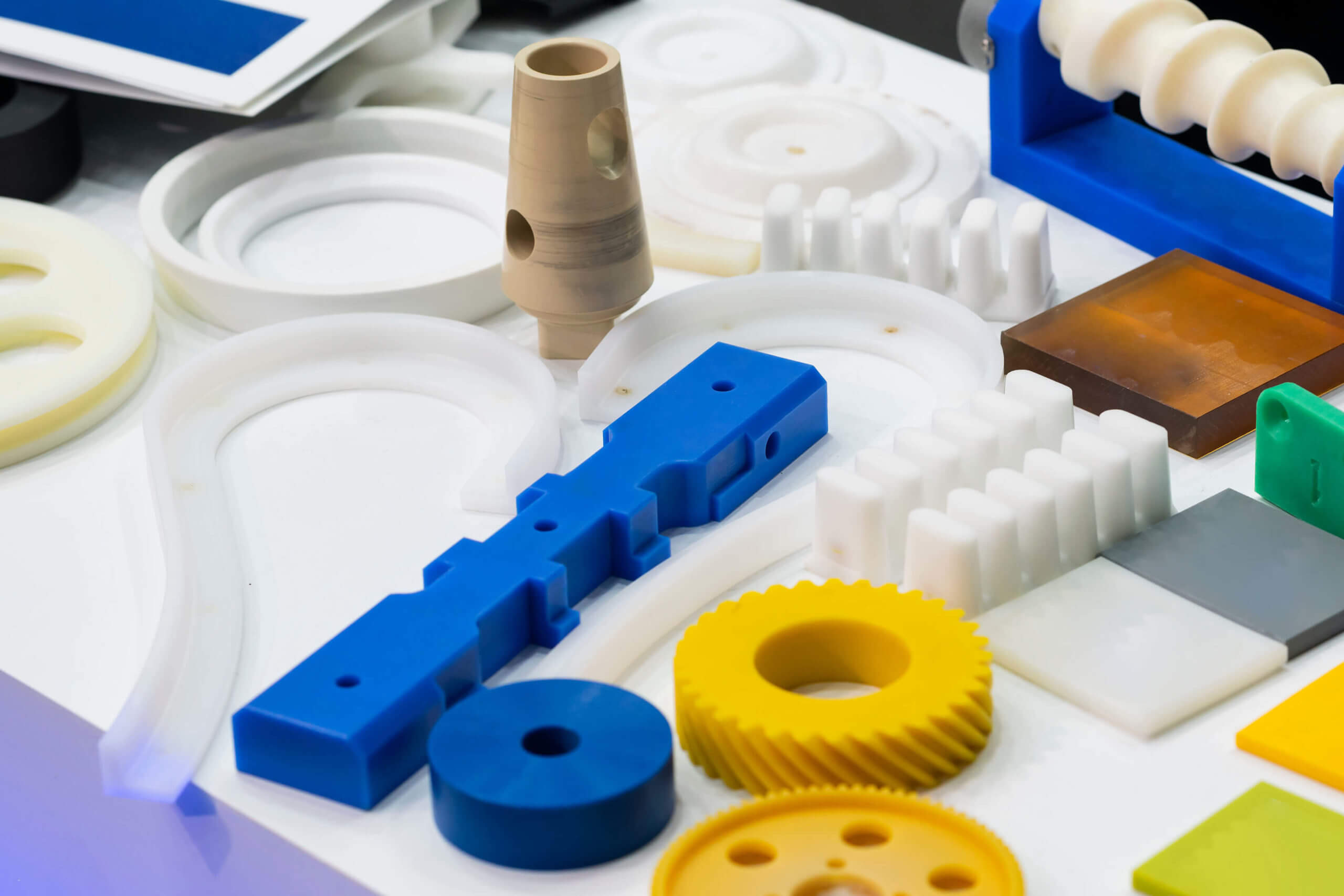
PTFE (polytetrafluoroethylene) is a standout material in high-performance engineering applications thanks to its remarkable chemical resistance, low coefficient of friction, and wide thermal operating range. These properties make PTFE ideal for use in seals, insulators, gaskets, and precision components found in various sectors, including medical, aerospace, semiconductor, and chemical processing. Its low mechanical strength, high thermal expansion, and tendency to deform under load create a unique set of challenges that can result in costly failures if not properly accounted for.

This article examines the most common and costly mistakes made during PTFE machining and provides guidance on how to avoid them.

Ignoring PTFE’s Thermal Expansion 

PTFE has a high coefficient of thermal expansion (CTE), ranging from 100 to 200 x 10^-6/°C. This is significantly higher than metals or rigid polymers. And a part machined at 22°C may expand or contract enough in service to cause critical dimensional shifts.

Failing to account for this thermal behavior during design and machining can result in components that seize, leak, or fail due to interference or clearance issues. Engineers must anticipate thermal conditions during part operation and adjust dimensions accordingly. In some cases, mating materials should also be chosen based on matched coefficients of thermal expansion (CTEs) to mitigate differential movement.

Not Accounting for Cold Flow (Creep) 

Cold flow, or creep, is the tendency of PTFE to slowly deform under constant mechanical stress. Unlike elastic deformation, creep is time-dependent and permanent. This behavior is especially problematic in applications involving sealing, clamping, or structural support.

When machining PTFE components, failure to design for creep can lead to reduced sealing force, shifting of components, or dimensional instability over time. For this reason, engineers should avoid thin unsupported walls and instead incorporate mechanical features that distribute load or accommodate long-term movement. Additionally, engineers should also minimize the presence of stress concentrations and increase the contact area between the PTFE part and the mating surface.

CNC Machine Operator
Caucasian CNC Machine Operator Wearing Blue Hard Hat and Safety Glasses. Industrial Concept.

Using Inappropriate Tooling and Feed Rates 

PTFE is soft and stringy, with a tendency to deform under tool pressure rather than shear cleanly. Standard tools may produce poor results, including smearing, tearing, or excessive burrs. Inappropriate tooling can also lead to tool chatter and vibration, which can affect surface finish and dimensional accuracy.

For optimal results, sharp carbide or HSS tools with positive rake angles around 0° to 15° should be used. Moderate feed rates help achieve clean cuts without excessive heat buildup. Tool paths should also be optimized to avoid chip welding or surface drag.

Over-Specifying Tolerances 

While PTFE can be machined to tight tolerances, its dimensional stability is limited by its thermal expansion and mechanical softness. Applying unnecessarily tight tolerances can increase machining time, tool wear, inspection failures, and scrap rate.

A tolerance of ±0.001″ may be achievable, but only under tightly controlled conditions. Design engineers should assess whether looser tolerances are acceptable based on function, especially for components that will operate in fluctuating thermal or pressure environments. When tight tolerances are required, consider post-machining inspection at operational temperature or even in the assembled state.

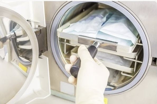
Skipping the Annealing Process 

Machining introduces residual stresses into PTFE, especially in deep cuts or during high-speed operations. These stresses can cause parts to warp or shrink unpredictably after machining. Annealing, which involves heating the material below its melting point and slowly cooling it, helps relieve these internal stresses.

Omitting this step can result in dimensional drift, especially for precision components or parts with asymmetrical features. For best results, anneal PTFE rods or billets before and sometimes after machining to ensure dimensional stability, especially in mission-critical applications.

Contaminating Parts with Coolants or Lubricants 

PTFE is chemically inert and non-absorbent, but its surface can trap oils, coolants, or metal debris. In industries like medical, food, or semiconductor manufacturing, even trace contaminants can cause product failure, rejection, or regulatory issues.

Machining PTFE is best done dry or with inert coolants (e.g., clean compressed air or specialty fluids). After machining, components should be thoroughly cleaned to remove surface residues. For highly sensitive applications, specify cleanroom-compatible handling and post-process inspection.

Inadequate Fixturing and Workholding 

Because PTFE is soft and deformable, improper clamping can lead to distortion during machining. Parts may spring back when unclamped, resulting in dimensional errors that are difficult to trace. Clamping too tightly can also leave marks or indentations that compromise function.

To prevent this, use soft jaws, vacuum fixtures, or contour-matched supports. Spread clamping forces over a larger area and avoid over-tightening. Designing the machining setup with minimal mechanical stress in mind is crucial for preserving the final part geometry.

The Answer to Mistakes in PTFE Machining

PTFE offers outstanding chemical resistance, temperature tolerance, and friction performance, but these benefits come with a price: complexity in machining. Failing to account for PTFE’s thermal expansion, creep, dimensional instability, and sensitivity to contamination can lead to part rejection, system failure, or compliance issues.

By understanding and mitigating these machining challenges, engineers and manufacturers can fully leverage the performance benefits of PTFE while maintaining cost-effective, reliable production. Whether you’re working with high-purity medical components, aerospace seals, or precision insulators, success lies in mastering the details of PTFE machining.

If you require expert support for precision-machined PTFE components or wish to explore custom-machined solutions, Advanced EMC Technologies offers the engineering expertise and production capabilities to ensure the success of your project.

by Sara McCaslin, PhD Sara McCaslin, PhD No Comments

What Sets Flexforce Canted Coil Springs Apart in High-Performance Applications

Canted coil springs, also known as slant coil springs, may be small in size, but their impact on engineering performance is substantial. Designed for multifunctionality, these springs serve critical roles in sealing, conductivity, mechanical latching, and load management. Flexforce, a proprietary line of canted coil springs offered by Advanced EMC Technologies, stands out for its exceptional precision, reliability, and adaptability across high-performance applications. 

This article examines the distinctive features of Flexforce springs and what distinguishes them in various industries, including aerospace and medical devices.

What Are Canted Coil Springs? 

Canted coil springs are composed of coils that are slanted (or canted) relative to the spring’s longitudinal axis, creating a unique geometry that enables uniform load behavior, consistent deflection characteristics, and multiple functional capabilities. Unlike more traditional springs, canted coil springs can maintain contact under highly variable tolerances and can be engineered for precise load-deflection profiles. Their design allows them to serve in sealing systems, act as conductive elements, enable mechanical locking mechanisms, and support high-cycle dynamic motion.

Defining the Flexforce Canted Coil Spring Difference

What makes Flexforce canted coil springs different? Here are five specific areas where the Flexforce makes a significant difference.

Precision Engineering and Manufacturing

Flexforce canted coil springs are produced with attention to consistency and quality. Advanced EMC Technologies employs precision manufacturing methods that ensure uniform coil spacing, tight dimensional tolerances, and high precision. This level of control is essential for mission-critical industries such as aerospace and medical devices, where even minor performance variation can result in system failure or safety risks.

Exceptional Load Control and Deflection Behavior

One of the key differentiators of Flexforce springs is their ability to maintain a nearly constant load across a wide range of deflection. This load-deflection stability enables engineers to design systems with predictable force behavior, whether under static compression, dynamic cycling, or thermal expansion. Flexforce springs can also be tailored to specific load profiles, ensuring optimal functionality in high-precision assemblies.

Multi-Functional Capabilities

Flexforce canted coil springs serve multiple roles within a single system. They provide spring-energizing force in sealing systems, enhancing the performance of PTFE and other polymer-based seals in extreme conditions. Additionally, they enable electrical conductivity, critical in applications such as EMI/RFI shielding and battery grounding. Their design also supports mechanical retention and latching, allowing for easy assembly and disassembly in components requiring secure but removable connections.

Customization and Material Versatility

Flexforce springs are available in a range of materials, including stainless steel, Elgiloy®, Hastelloy®, and other high-performance alloys. These materials offer varying levels of corrosion resistance, strength, and temperature tolerance. For applications requiring electrical conductivity or specialized environments, coatings can be applied to enhance performance. Flexforce also offers custom spring geometries and load curves to meet the unique demands of each application.

Design and Integration Advantages

Flexforce springs are designed with integration in mind. Their compact size and flexible design parameters allow engineers to incorporate them into existing designs without extensive modifications. Assembly is simplified, resulting in reduced labor time and costs. Additionally, their high reliability lowers maintenance needs and extends service intervals, which is particularly important in industries where downtime is costly.

FlexForce™ canted coil springs by Advanced EMC Technologies offer versatile solutions across multiple industries.

Flexforce Canted Coil Spring Performance in Critical Industries

Medical Devices

In medical technology, miniaturization and reliability are non-negotiable. Flexforce springs meet these demands with high precision and cleanliness. Their ability to function reliably in compact designs with low particulate generation makes them suitable for use in surgical robotics, implantable devices, diagnostic tools, and precision instruments. Biocompatible materials and cleanroom-friendly manufacturing further position Flexforce as a leader in medical spring solutions.

Aerospace and Space Exploration

Flexforce springs are engineered for the extreme conditions of aerospace and space applications. They operate reliably under vacuum conditions, extreme temperatures, and mechanical vibrations. In spacecraft and satellite systems, they are commonly used in spring-energized seals, electrical connectors, and latch mechanisms. Their high cycle life and performance under thermal and mechanical stress ensure continued operation in environments where failure is not an option.

Renewable Energy and EV Applications

In the renewable energy and electric vehicle (EV) sectors, Flexforce springs are utilized to manage electrical pathways, ensure electromagnetic interference (EMI) shielding, and support mechanical functions in high-vibration environments. Their resistance to fatigue and consistent load behavior make them ideal for dynamic systems, including battery packs, connectors, and control units. As EV and renewable energy technologies continue to advance, the demand for robust, multifunctional spring components, such as Flexforce, will only increase.

Why Engineers Choose Flexforce Canted Coil Springs

Engineers and OEMs choose Flexforce canted coil springs due to their proven performance and adaptability. Advanced EMC supports its Flexforce product line with engineering consultation, custom design services, and rigorous quality assurance. Whether the need is for a high-reliability seal in space or a low-resistance conductive spring in a medical device, Flexforce provides a dependable solution that can be tailored to meet exact specifications.

Conclusion 

Flexforce canted coil springs are more than just components—they are enablers of performance, reliability, and innovation across high-stakes industries. Their precision construction, multi-functional capabilities, and customizability set them apart in the world of engineered spring solutions. For engineers seeking consistent performance under extreme conditions, Flexforce delivers. Contact Advanced EMC Technologies to learn how Flexforce springs can elevate your next high-performance design.