A specification that simply calls out “flouropolymer” is quite incomplete. PVDF and PTFE are both fluoropolymers and grouped under that umbrella term, but they are quite different. When it comes to mechanical and chemical behavior, specifying the wrong material can lead to premature seal failure and expensive downtime. The objective of this blog post is to provide a clear, practical basis for determining which material is the most appropriate.
How PVDF and PTFE Are the Same
Both PVDF (Kynar) and PTFE (Teflon) resist a broad range of acids and solvents, and both handle highly elevated temperatures better than elastomers. They also share low coefficients of friction, low surface adhesion, and non-stick properties. And both have their own specialties in fluid-handling applications.
Where PVDF Pulls Ahead of PTFE
PVDF (Polyvinylidene Fluoride) has distinct advantages over PTFE (Polytetrafluoroethylene). It exhibits better mechanical strength than PTFE (by about 2-3x) and has excellent abrasion resistance, which means it can hold up better under slurry or particulate-laden fluid flow. Wear resistance is another property of PVDF that excels over PTFE, especially in dynamic seal contact, such as wear sleeves and piston rings. It also exhibits lower cold flow and creep under compression, which is very important for seal performance over time under sustained load.
Finally, PTFE might be more expensive than the equivalent PVDF stock. While PTFE stock is inexpensive, PVDF is melt-processable. Being melt-processable can make PVDF vastly more cost-effective for high-volume molded parts.
Where PVDF Loses Against PTFE
PTFE has an extremely low coefficient of friction compared to PVDF (0.04-0.10 vs. 0.15-0.30). And in the presence of high-pH caustics and strong bases, PTFE performs without issue, whereas PVDF begins to degrade. There are also polar solvents, amines, fuming acids, and some ketones that attack PVDF’s chemical structure and polymer chain. PVDF’s chemical resistance chart has real gaps where PTFE’s is closer to “resistant to everything below its temp limit.” Always check material compatibility at your actual operating temperature, not ambient temperature. It is a fact that many “resistant” ratings degrade at elevated temperatures.
PVDF vs PTFE – Who Wins?
The table below summarizes the similarities and differences between PVDF and PTFE.
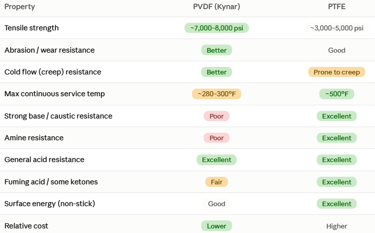
*Values are approximate; exact values are based on material grade and blend
* PVDF: Lower for high-volume molding; PTFE: Lower for machined stock
Decision framework
Here is a checklist for fluid handling engineers choosing between PVDF and PTFE:
- What’s touching the seal? Check for a strong base or problem solvent first; if it is present, PTFE wins outright
- Is there abrasive/particulate content or high dynamic wear? If so, lean toward PVDF if the compatibility allows
- Is the seal under sustained compressive load where creep matters? If so, lean toward PVDF
- Static seal, clean chemistry, wide chemical exposure risk (multi-product lines, CIP/COP)? PTFE is the safer default.
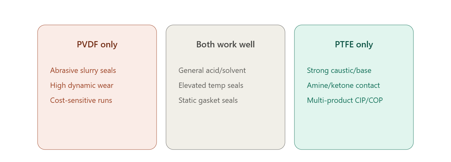
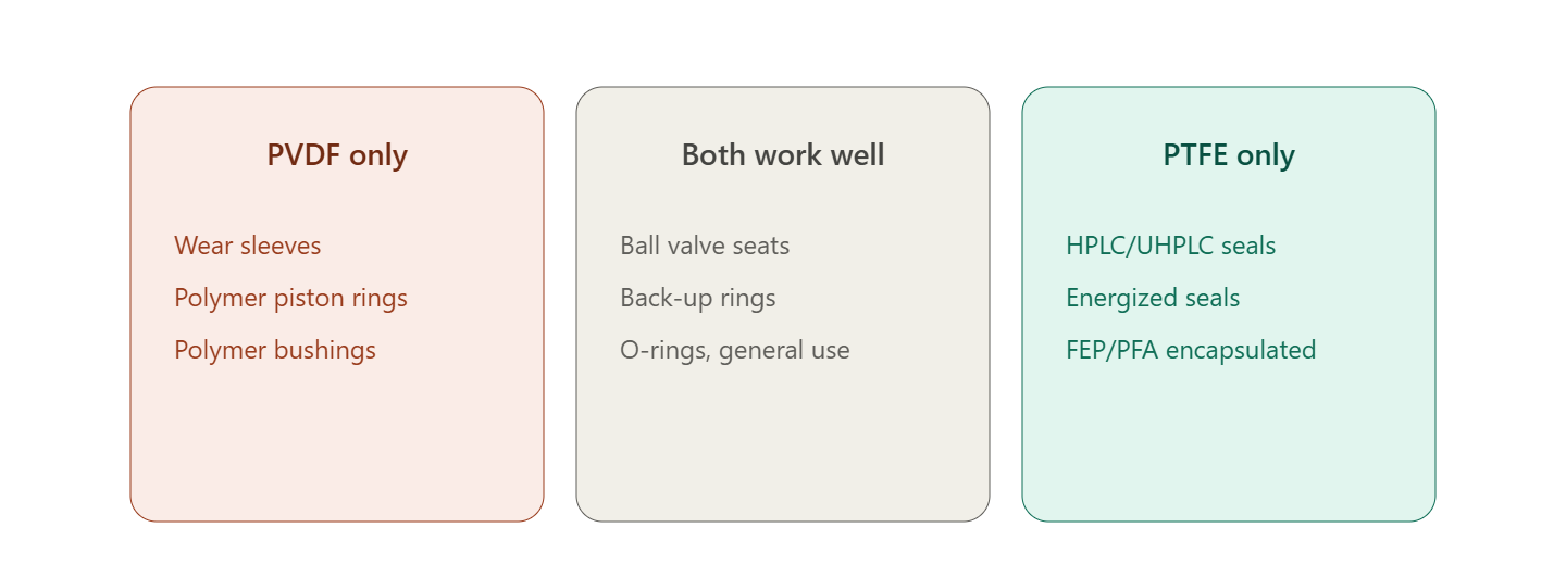
The figures below show examples of where each material performs best.
Conclusion
Borderline cases with mixed process streams, elevated-temperature caustics, or unusual solvent blends are exactly where a materials engineer should get involved before committing to tooling. It is always cheaper to change a decision on paper than after seals are cut. Advanced EMC is here to help you choose the right material and seal for your fluid-handling challenges. And keep in mind that Advanced EMC offers several material options if neither material is a fit.