Elastomer seals are effective in many industrial applications. They are cost-effective, forgiving to install, and reliable across a surprisingly wide range of conditions. Push them into cryogenic temperatures, though, and you stop troubleshooting a maintenance issue and start managing a system failure.
This post breaks down the five primary failure modes that render elastomers unsuitable for cryogenic environments along with some of the alternative solutions that engineers are implementing in their designs.
Why Elastomers Make Effective Seals
Elastomers are effective as seals primarily because of their polymer chain structure. Long, flexible molecular chains in elastomers are able to compress under load and still spring back, filling the microscopic gaps in a mating surface. That recovery force is what creates the seal. Remove the conditions that keep those chains mobile and flexible, and the entire sealing mechanism falls apart.
Cryogenic Failure Mode 1: Glass Transition and Brittleness
Every elastomer has a glass transition temperature (Tg); below it, polymer chains lose mobility. In short, the material stops behaving like rubber and starts behaving like glass: brittle, fragile, unable to recover from deformation.
For Buna-N (NBR), for example, that glass transition threshold sits around -40°C. Viton (FKM), on the other hand, fares slightly worse, typically losing flexibility above -20°C. Liquid nitrogen service operates at -196°C, while liquid hydrogen reaches -253°C and liquid helium reaches -269°C. Standard elastomers do not just underperform at those temperatures but become dangerous (and expesnive) mechanical hazards. A seal that shatters during assembly, or its first thermal cycle, introduces contamination and creates a safety event, not simply a leakage problem.
Cryogenic Failure Mode 2: Compression Set
A seal works by staying compressed, and compression set is what happens when the material cannot fully return to its original shape after prolonged loading. You can think of it as the seal losing the memory of what it used to look like. Now, cold temperatures accelerate this dramatically. Polymer chain mobility drops near the glass transition point, and a seal that was properly loaded at installation may lose its recovery force entirely after just one deep thermal cycle. Each subsequent cycle makes compression set worse. What starts as an acceptable leak rate at commissioning can quickly drift well outside specification after a handful of cooling and warming cycles, with no visible mechanical failure to indicate the problem. This can quickly lead to catastrophic failure.
Cryogenic Failure Mode 3: Thermal Cycling Fatigue
Thermal cycling fatigue often gets mistaken for compression set, but it operates through a different mechanism. The core problem this failure mode is differential thermal expansion between the seal and the surrounding hardware. Most elastomers expand and contract at rates several times higher than stainless steel or aluminum.
As temperatures fluctuate, the seal and flange expand and contract at different rates. In cryogenic valve applications specifically, where seals may cycle repeatedly between ambient and operating temperatures, this mismatch eventually induces micro-cracking at the seal surface and progressively erodes the contact stress at the sealing interface. The seal may look intact, but the leak rate tells a significantly different story.
Cryogenic Failure Mode 4: Outgassing and Vacuum Contamination
In vacuum environments, the failure mode shifts from mechanical to molecular. Elastomers contain residual plasticizers, curing agents, and processing residues, and under vacuum, these volatiles release trapped molecules into the chamber. For applications in semiconductor fabrication, particle accelerators, or analytical instrumentation, outgassing not only raises base pressure but it simultaneously contaminates process gases or sensitive surfaces. Elastomers rated for vacuum service reduce this problem but cannot eliminate it. Virgin PTFE and high-purity fluoropolymer materials meet NASA and ESA standards for minimal outgassing and perform reliably under ultra-high vacuum conditions.
Cryogenic Failure Mode 5: Permeation
Most engineers think of seal leakage as a gap problem. However, with elastomers, that explanation is actually incomplete. Gas molecules can actually dissolve into the polymer matrix on the high-pressure side and diffuse through the bulk material to the low-pressure side, and all with no gap required.
Permeation is especially problematic in cryogenic hydrogen service. Hydrogen is the smallest diatomic molecule in existence and thus diffuses through more materials than almost any other gas. An elastomer that tests acceptably with nitrogen can still fail badly with hydrogen, and the consequences extend beyond leakage: prolonged hydrogen permeation into metal housings contributes to embrittlement of those components over time, as well.
What Engineers Are Specifying Instead of Elastomer Seals
The answer to cryogenic sealing is rarely one-size-fits-all. The fact is the right replacement depends on the specific application, operating fluid, temperature range, and whether the seal is in a static or dynamic interface. On the plus side, several proven options can address sealing issues that elastomers cannot.
PTFE spring-energized seals are widely used in cryogenic hydrogen systems, cryogenic valve assemblies, and space applications where outgassing, permeation resistance, and low-temperature flexibility all matter. The PTFE jacket remains dimensionally stable and chemically inert at temperatures approaching -253°C, while the internal metallic spring energizer is able to maintain a consistent sealing force even as hardware contracts during cooldown. Energizer geometry is selected based on application requirements: helical springs suit low-temperature and vacuum conditions, cantilever designs work well for lighter dynamic loads, and canted coil configurations handle higher-pressure environments. For cryogenic valves in particular, the spring-energized seal design compensates for the dimensional shifts that occur during repeated thermal cycling without requiring retorquing or adjustment.
FEP-encapsulated helical spring O-rings take a different approach to the same problems. A stainless steel flat-wound helical spring core is completely encapsulated in a seamless FEP (fluorinated ethylene propylene) jacket. The FEP provides the necessary chemical inertness and cryogenic flexibility while the spring eliminates compression set by maintaining a consistent sealing load mechanically (independent of what the jacket material does under thermal stress). This type of cryogenic sealing solution is a common choice in valve assemblies, turbopump flanges, and liquid oxygen and liquid hydrogen feed lines in launch systems. The combination of (1) a non-relaxing spring core and (2) a chemically resistant outer jacket makes them very well-suited to applications involving repeated pressure and temperature transitions.
PTFE and its variants, including PCTFE and TFM, are the standard material group for cryogenic seals used in marine loading arms. In these extremely harsh environments, seals must survive continuous exposure to liquefied petroleum gas, liquefied natural gas, liquid oxygen, liquid nitrogen, and liquid hydrogen during critical loading and unloading operations. PTFE and its variants provide extremely broad chemical compatibility, very low friction, self-lubricating behavior, and the dimensional stability necessary to function reliably at temperatures as low as -269°C. Torlon polyamide-imide is another option for applications requiring rigidity and structural stability even at cryogenic extremes.
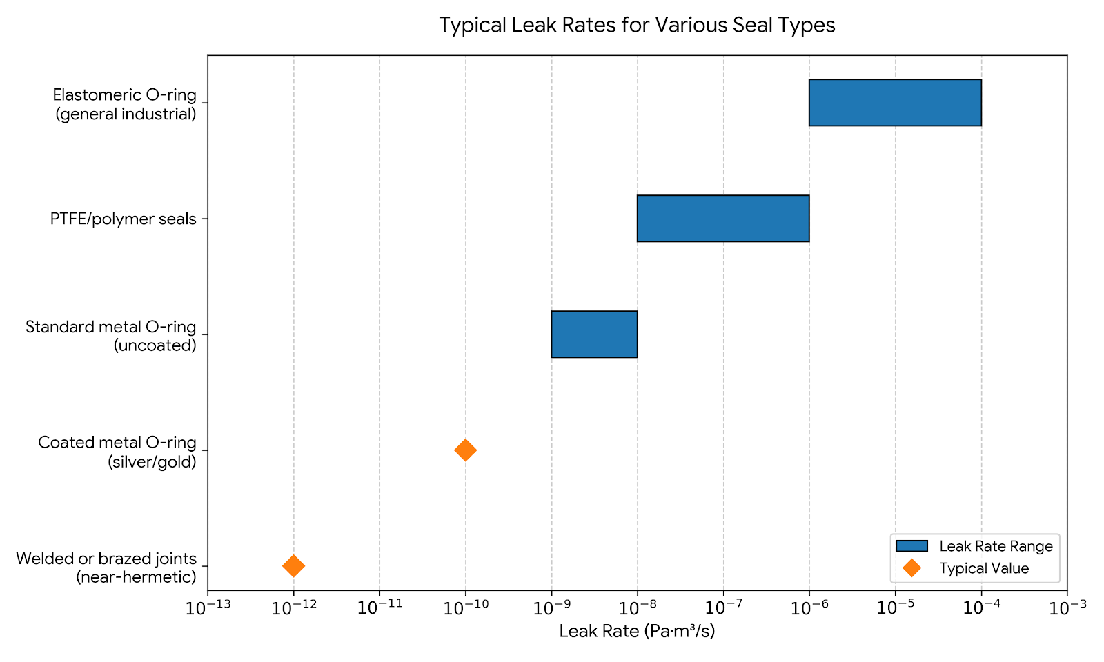
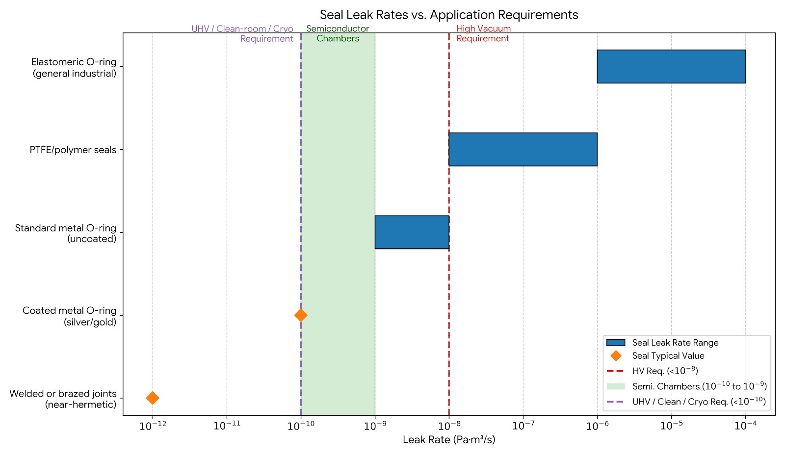
Metal seals, including C-rings and other spring-energized metal profiles, solve the outgassing and permeation problems entirely. Metal produces no outgassing and is impermeable to gas diffusion. The tradeoff is real, however: metal seals require tighter flange tolerances, controlled surface finish, and higher seating loads. For ultra-high vacuum or cleanroom environments where those parameters can be controlled, the performance advantage of implementing a metal seal become clear.
Conclusion
None of the solutions presented here is the “perfect” answer to the harsh, demanding environment of cryogenic seals. However, PTFE spring-energized seals offer excellent flexibility and chemical resistance with relatively forgiving installation requirements. FEP-encapsulated designs, on the other hand, share similar chemical properties with PTFE and include the added resilience of a spring core that does not relax over time. PTFE-based seals in their various formulations cover marine, valve, and general cryogenic service across a wide range of media. And metal seals offer the lowest possible leakage rates and zero outgassing, but at the cost of tighter system-level tolerances.
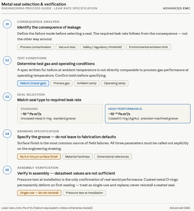
The most common engineering mistake in this design space is treating the elastomer swap as a drop-in substitution. Groove geometry, surface finish requirements, and seating load all must be revisited when switching seal types, and the coefficient of thermal expansion of the replacement material must be accounted for during installation.
If your application involves cryogenic temperatures, hard vacuum, or both, the sealing specialists at Advanced EMC can help identify the right seal type, material, and groove specification for your design. Contact us to get started.