Metal seals step in when high-performance polymer seals simply cannot withstand environmental conditions. Metal ring seals are engineered for environments that would quickly degrade, deform, or destroy equivalent elastomeric and polymer alternatives.
From cryogenic liquid hydrogen lines at –270°C or high-pressure wellhead equipment at 300 MPa, to jet engine components cycling through extreme thermal gradients, a correctly specified metal seal delivers reliable, near-zero-leakage performance when nothing else can.
This article looks at the most common types of metal used, along with a brief introduction to the various types of metal seals.
Understanding Metal Seal Types
Before choosing a material for a metal seal, it helps to understand how seal geometry interacts with material properties. Advanced EMC Technologies offers three primary metal O-ring configurations, and each places different demands on the base alloy.
Standard Metal O-Ring Seals rely on controlled plastic deformation at installation. The seal compresses against the mating groove, and the metal’s inherent springback generates the sealing force. Because of their high strength, they provide extremely reliable sealing solutions for applications that involve high pressure, extreme temperatures, and vacuum conditions. And with minimal springback, this seal is ideal for static sealing across a range of industries. They are often used with exhaust systems, static flange seals, and static seals for equipment.
Because this design depends on the metal’s elastic and yield properties, the alloy must be ductile enough to deform without cracking and possess sufficient stiffness to maintain residual stress over time. That can be a challenging balance to strike.
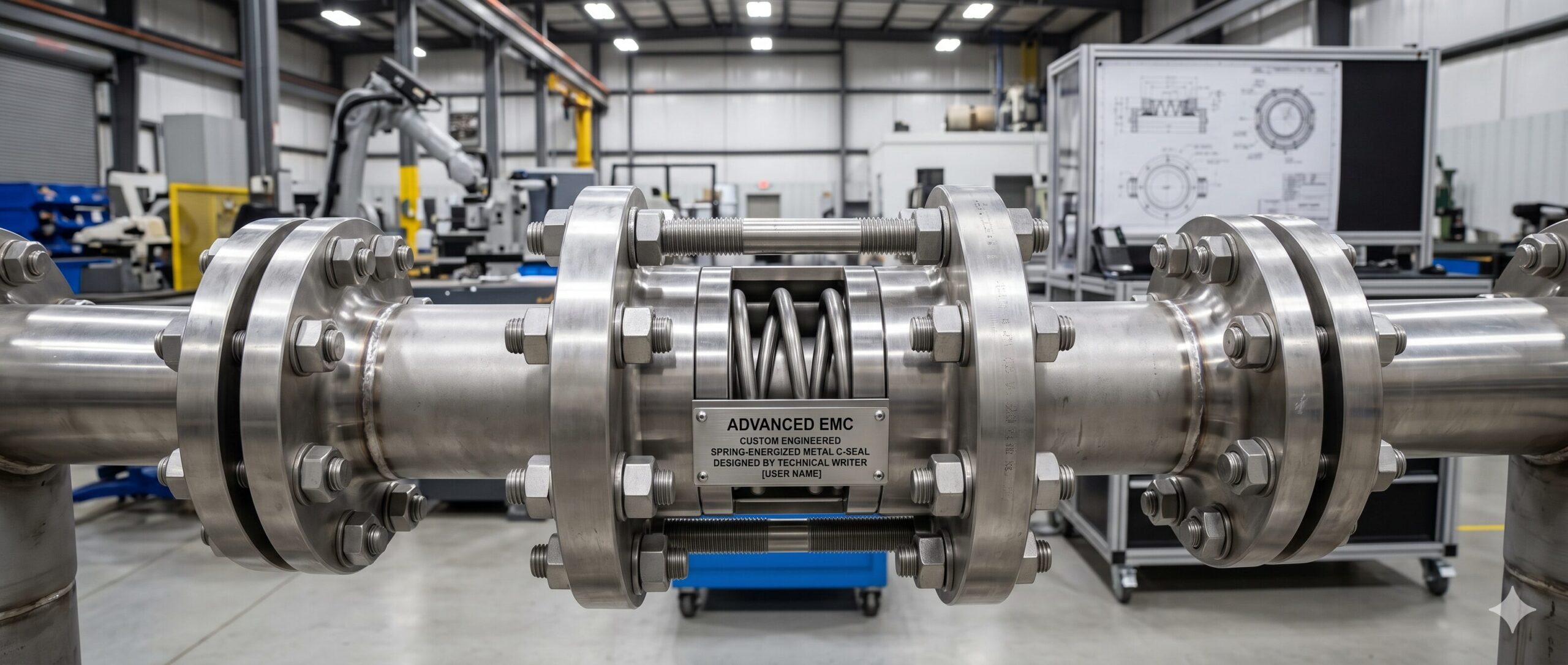
There are also Spring-Energized Metal O-Ring Seals, which combine a hollow metallic tube with an internal spring, which maintains sealing force even under thermal cycling or pressure fluctuations. With its enhanced flexibility and lower leakage rate, this configuration is ideal for high-pressure cryogenic service or applications that experience significant temperature swings. These seals are engineered for some of the harshest working environments out there, and are well-adapted to
- High-Pressure Fuel Systems
- Cryogenic Sealing
- Wellhead Seals
- Pipeline Flanges
- Steam Turbine Sealing
Keep in mind, however, that the material selection for spring-energized metal O-ring seals must account for both the outer tube alloy and the spring alloy, which are often different.
Balanced Metal O-Ring Seals use vented holes that allow system pressure to augment the sealing contact force and were developed for applications involving high pressure and temperature. The pressure-activated design is well-suited to static, high-pressure applications where the seal may see variable loading. Here, corrosion resistance of the entire seal body, including the internal surfaces exposed to process media through the vents, becomes a critical selection factor. Balanced metal o-ring seals are an excellent choice for pressure vessels and pressure-activated seals.
Common Metal Seal Materials
The materials discussed below are among the most frequently specified for metal seals across industrial, aerospace, and energy applications.
Stainless Steels
The stainless steel family offers a reliable starting point for a broad range of standard sealing applications. These steel alloys combine good mechanical strength, reasonable corrosion resistance, and wide availability. This makes them the default choice material for metal seals when operating conditions do not demand something more specialized.
321 Stainless Steel is stabilized with titanium, which prevents sensitization, a form of grain-boundary corrosion that can occur in standard 304 SS after its exposure to elevated temperatures. This makes 321 SS particularly well-suited for seals experiencing intermittent or sustained heat exposure, such as in exhaust systems, heat exchangers, and power generation equipment. The resistance of 321 SS to intergranular corrosion makes it a more durable long-term metal seal option than unstabilized grades when used in thermal cycling applications.
347 Stainless Steel is stabilized with niobium. It offers similar sensitization resistance to 321 SS, but with slightly better high-temperature strength. It is commonly specified for applications in the 425°C to 870°C range, especially where weld decay is a concern, and the seal must maintain its mechanical properties through repeated thermal cycling. The aerospace and chemical processing industries use 347 SS metal seals for these reasons.
316L Stainless Steel is the low-carbon version of the 316 alloy. The reduced carbon content in 316L SS minimizes issues with carbide precipitation during welding and heat treatment. This, in turn, improves resistance to intergranular corrosion. Molybdenum provides excellent resistance to chlorides as well as pitting. This, in turn, makes 316L SS a good choice for marine environments, pharmaceutical processing, and food-grade applications where cleanliness and corrosion performance are priorities. When moderate chemical exposure is involved, and the goal is a balance of weldability, strength, and corrosion resistance, 316L stainless steel is usually the first alloy considered for the metal seals.
Inconel Alloys
When temperatures climb beyond the practical limits of stainless steel, nickel-based superalloys come into consideration. The Inconel family is specially engineered to retain mechanical integrity in conditions that would cause standard alloys to oxidize, creep, or fail.
Inconel 600 is a nickel-chromium alloy with outstanding resistance to oxidation and carburization at high temperatures. It offers very reliable performance from cryogenic temperatures through approximately 1,093°C, making it one of the most thermally capable alloys available for sealing applications. Inconel 600 is very resistant to chloride-ion stress-corrosion cracking (a failure mode that can affect stainless steels in certain environments), and it performs well in both oxidizing and reducing atmospheres. Inconel 600 is frequently specified for metal seals in nuclear engineering, heat treating equipment, and chemical processing applications where broad thermal stability is required alongside corrosion resistance.
Inconel 718, on the other hand, is probably the most widely used superalloy for metal seals in aerospace and turbine engineering. Its precipitation-hardened microstructure proves excellent tensile strength, fatigue resistance, and creep resistance. And all of this at temperatures up to approximately 700°C. What sets Inconel 718 further apart is both its high-temperature capability and its weldability, which is a property that many other superalloys lack. Inconel 718 is easier to fabricate into complex seal geometries and assemblies. For gas turbine seals, jet engine components, high-pressure fuel systems, and cryogenic liquid propellant lines, Inconel 718 is an excellent option, and its high yield strength also makes it well-suited to extremely high-pressure sealing environments.
Hastelloy C-276
When aggressive chemicals are the primary threat, Hastelloy C-276 stands apart from virtually every other common alloy. This nickel-molybdenum-chromium alloy was specifically developed to resist a wide spectrum of corrosive media, including wet chlorine, chloride solutions, hypochlorite, sulfuric acid, hydrochloric acid, and hydrogen sulfide (H₂S).
Keep in mind that in oil and gas applications, there are sour gas wells containing H₂S, one of the most aggressive corrosion environments in industry. Standard stainless steels and even many nickel alloys can suffer from stress-corrosion cracking or sulfide stress cracking under these conditions. Hastelloy C-276, however, resists both. It is the preferred material for wellhead seals, downhole components, and offshore processing equipment exposed to sour service conditions.
In chemical processing, Hatelloy C-276’s resistance extends to strongly oxidizing acids at elevated temperatures, a combination that eliminates most alternative materials from consideration. When the process media is the unknown variable, or when it is known to be aggressive, Hastelloy C-276 is typically the safest and most cost-effective long-term choice for the metal seals.
Titanium
Titanium offers corrosion resistance comparable to many nickel alloys at roughly 40% of the weight of stainless steel. This low density makes it a good choice in SWaP aerospace and defense applications where every gram of weight impacts fuel consumption, payload capacity, or structural loading.
Titanium forms a stable, self-healing oxide layer that resists attack from seawater, chloride solutions, nitric acid, and a wide range of organic compounds. It performs well as a seal material across a broad temperature range, and it also maintains good ductility, which is important for achieving the controlled deformation that metal seals require at installation. For aircraft structural seals, spacecraft fluid systems, submarine components, and marine hardware, titanium metal seals offer a good combination of performance and weight efficiency that stainless steel cannot match. It is also fully biocompatible, making it a viable option for medical device applications where metallic sealing is required.
Soft Metals
Not every sealing application demands high strength or extreme temperature capability. In lower-pressure, lower-temperature environments, or where the mating flange surfaces have imperfect finishes, the metal seal design priority shifts from strength to conformability. Soft metals excel in such applications because their ductility lets them make extensive contact with surface irregularities and establish effective metal-to-metal contact with a minimal seating load.
Copper is one of the oldest and most reliable soft metal seal materials. It offers excellent thermal conductivity, good electrical conductivity, and sufficient ductility to conform to moderate surface finish variations. Copper seals are widely used in heat exchanger flanges, steam systems, hydraulic fittings, and electrical pass-through seals. Oxygen-free copper grades are specified where outgassing in vacuum environments must be minimized.
Nickel, on the other hand, occupies the middle ground between the soft metals and engineering alloys. It is harder than copper or aluminum but still ductile enough for conformability-driven applications. Nickel seals provide better corrosion resistance than copper in many environments. They are often used in chemical processing, food and beverage equipment, and applications requiring FDA-compliant materials.
Aluminum seals are lightweight and highly conformable. They offer sufficient corrosion resistance for use as metal seals in pneumatic systems, vacuum chambers, and non-aggressive fluid systems. Their relative softness requires a minimal seating force, a distinct advantage in precision instrumentation applications and delicate assemblies where over-compression could damage the housings. Aluminum seals are commonly found in laboratory equipment, semiconductor process chambers, and aerospace fluid systems.
Silver has the highest thermal and electrical conductivity of any metal, and its extreme softness means it can conform to even rough or slightly damaged flange surfaces. Silver-plated or solid silver seals are often specified in ultra-high-vacuum systems, cryogenic service, nuclear applications, and any environment requiring the absolute lowest leakage rates achievable with a metal seal. The cost premium of using silver metal seals is justified by silver’s unmatched ability to seal surfaces that would reject harder materials.
The Role of Surface Coatings
Surface coatings are another important aspect of successful metal seals. The four most common surface coatings are silver, gold, PTFE, and nickel. Silver plating, which happens to be the most common, is used to improve how well the seal conforms to hard mating surfaces (e.g., hard stainless steel or alloy steel) and provides a level of corrosion protection.
Gold plating is preferred when ultra-low leakage is necessary, and is often used in cleanrooms and semiconductor fabrication processes. Gold plating also aids in minimizing outgassing where contamination is a serious concern and works extremely well in vacuum conditions.
Both PTFE and nickel coatings can provide protection against aggressive chemicals while also reducing the probability of galling. PTFE aids in reducing friction and offers additional chemical resistance. Electroless nickel plating, on the other hand, improves surface hardness and enhances the corrosion resistance of stainless steel alloy substrates.
Partnering with Advanced EMC Technologies
At Advanced EMC, we understand the challenges related to designing metal seals. We offer engineering collaboration from first contact, helping you select the right sealing solution for your application. With ISO, AS9100D, and NORSOK qualifications, you can count on us to help you navigate the often complex standards and best practices for your seals. Contact Advanced EMC to learn more about what we offer and to experience our customer service firsthand.