
by Daniel Mays Daniel Mays No Comments

Avoiding Costly Mistakes in PTFE Machining: A Guide for Design Engineers

Mistakes in PTFE machining can be surprisingly costly, despite the material’s reputation as a high-performance solution. PTFE (polytetrafluoroethylene) is valued for its exceptional chemical resistance, low coefficient of friction, and wide thermal operating range.

PTFE (polytetrafluoroethylene) is a standout material in high-performance engineering applications thanks to its remarkable chemical resistance, low coefficient of friction, and wide thermal operating range. These properties make PTFE ideal for use in seals, insulators, gaskets, and precision components found in various sectors, including medical, aerospace, semiconductor, and chemical processing. Its low mechanical strength, high thermal expansion, and tendency to deform under load create a unique set of challenges that can result in costly failures if not properly accounted for.

This article examines the most common and costly mistakes made during PTFE machining and provides guidance on how to avoid them.

Ignoring PTFE’s Thermal Expansion 

PTFE has a high coefficient of thermal expansion (CTE), ranging from 100 to 200 x 10^-6/°C. This is significantly higher than metals or rigid polymers. And a part machined at 22°C may expand or contract enough in service to cause critical dimensional shifts.

Failing to account for this thermal behavior during design and machining can result in components that seize, leak, or fail due to interference or clearance issues. Engineers must anticipate thermal conditions during part operation and adjust dimensions accordingly. In some cases, mating materials should also be chosen based on matched coefficients of thermal expansion (CTEs) to mitigate differential movement.

Not Accounting for Cold Flow (Creep) 

Cold flow, or creep, is the tendency of PTFE to slowly deform under constant mechanical stress. Unlike elastic deformation, creep is time-dependent and permanent. This behavior is especially problematic in applications involving sealing, clamping, or structural support.

When machining PTFE components, failure to design for creep can lead to reduced sealing force, shifting of components, or dimensional instability over time. For this reason, engineers should avoid thin unsupported walls and instead incorporate mechanical features that distribute load or accommodate long-term movement. Additionally, engineers should also minimize the presence of stress concentrations and increase the contact area between the PTFE part and the mating surface.
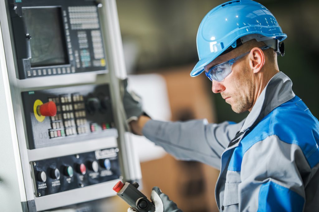
CNC Machine Operator
Caucasian CNC Machine Operator Wearing Blue Hard Hat and Safety Glasses. Industrial Concept.

Using Inappropriate Tooling and Feed Rates 

PTFE is soft and stringy, with a tendency to deform under tool pressure rather than shear cleanly. Standard tools may produce poor results, including smearing, tearing, or excessive burrs. Inappropriate tooling can also lead to tool chatter and vibration, which can affect surface finish and dimensional accuracy.

For optimal results, sharp carbide or HSS tools with positive rake angles around 0° to 15° should be used. Moderate feed rates help achieve clean cuts without excessive heat buildup. Tool paths should also be optimized to avoid chip welding or surface drag.

Over-Specifying Tolerances 

While PTFE can be machined to tight tolerances, its dimensional stability is limited by its thermal expansion and mechanical softness. Applying unnecessarily tight tolerances can increase machining time, tool wear, inspection failures, and scrap rate.

A tolerance of ±0.001″ may be achievable, but only under tightly controlled conditions. Design engineers should assess whether looser tolerances are acceptable based on function, especially for components that will operate in fluctuating thermal or pressure environments. When tight tolerances are required, consider post-machining inspection at operational temperature or even in the assembled state.

Skipping the Annealing Process 

Machining introduces residual stresses into PTFE, especially in deep cuts or during high-speed operations. These stresses can cause parts to warp or shrink unpredictably after machining. Annealing, which involves heating the material below its melting point and slowly cooling it, helps relieve these internal stresses.

Omitting this step can result in dimensional drift, especially for precision components or parts with asymmetrical features. For best results, anneal PTFE rods or billets before and sometimes after machining to ensure dimensional stability, especially in mission-critical applications.

Contaminating Parts with Coolants or Lubricants 

PTFE is chemically inert and non-absorbent, but its surface can trap oils, coolants, or metal debris. In industries like medical, food, or semiconductor manufacturing, even trace contaminants can cause product failure, rejection, or regulatory issues.

Machining PTFE is best done dry or with inert coolants (e.g., clean compressed air or specialty fluids). After machining, components should be thoroughly cleaned to remove surface residues. For highly sensitive applications, specify cleanroom-compatible handling and post-process inspection.

Inadequate Fixturing and Workholding 

Because PTFE is soft and deformable, improper clamping can lead to distortion during machining. Parts may spring back when unclamped, resulting in dimensional errors that are difficult to trace. Clamping too tightly can also leave marks or indentations that compromise function.

To prevent this, use soft jaws, vacuum fixtures, or contour-matched supports. Spread clamping forces over a larger area and avoid over-tightening. Designing the machining setup with minimal mechanical stress in mind is crucial for preserving the final part geometry.

The Answer to Mistakes in PTFE Machining

PTFE offers outstanding chemical resistance, temperature tolerance, and friction performance, but these benefits come with a price: complexity in machining. Failing to account for PTFE’s thermal expansion, creep, dimensional instability, and sensitivity to contamination can lead to part rejection, system failure, or compliance issues.

By understanding and mitigating these machining challenges, engineers and manufacturers can fully leverage the performance benefits of PTFE while maintaining cost-effective, reliable production. Whether you’re working with high-purity medical components, aerospace seals, or precision insulators, success lies in mastering the details of PTFE machining.

If you require expert support for precision-machined PTFE components or wish to explore custom-machined solutions, Advanced EMC Technologies offers the engineering expertise and production capabilities to ensure the success of your project.
by Daniel Mays Daniel Mays No Comments

When to Choose Auto Molding for PTFE Components

If efficiency, precision, and scalability are crucial for your design, auto molding for PTFE components can provide a distinct advantage over traditional molding methods. It is commonly used in industries where performance and consistency are non-negotiable, and this manufacturing process is ideal for producing high volumes of complex, tight-tolerance parts. 

In this article, we examine when auto molding is the optimal choice for producing PTFE components.

Understanding Auto Molding for PTFE

Auto molding, also known as automatic molding, is a high-efficiency process used to manufacture PTFE components at scale. Unlike the labor-intensive, low-volume traditional compression molding, auto molding supports automated, high-throughput production runs. This process leverages precision tooling and automated pressing systems to form consistent, repeatable components with minimal human intervention.

The method is particularly well-suited for producing a wide range of PTFE parts such as seals for medical devices, seats for aerospace systems, bushings for semiconductor manufacturing, and insulators for various applications—components that often require tight dimensional tolerances and uniform performance. Auto molding can accommodate a variety of PTFE-based materials, including filled and modified PTFE compounds, depending on the application’s mechanical, thermal, or chemical resistance requirements.

What sets modern auto molding apart is its integration with downstream operations such as automatic trimming, quality inspection, and packaging. Such features not only reduce cycle times but also improve part consistency across batches, making them ideal for demanding sectors such as medical devices, semiconductor manufacturing, and aerospace systems.

Basic Steps in the PTFE Auto Molding Process

  1. Create Molds
    Tool and die makers can fabricated the molds through various methods such as precision machining, die casting, or advanced techniques like 3D printing. The mold design must support tight tolerances and repeatability to ensure accurate and consistent product quality.
  2. Set Up the Machine
    Prepare the molding equipment by cleaning the molds, preheating as necessary, and configuring the press settings according to the material and part geometry.
  3. Prepare the Charge
    Select the appropriate PTFE material—virgin or filled—and measure the correct amount. Oversized charges can lead to flash formation, which may require post-processing.
  4. Insert the Charge
    Place the material charge at the center of the bottom mold cavity to ensure uniform compression.
  5. Compress the Part
    Close the mold and apply the necessary pressure, often in combination with heat, to shape the component. Heating improves material flow and reduces cycle time.
  6. Release the Part
    Once the part is fully formed and cooled, open the mold and remove the molded component.
  7. Clean and Finish
    Trim any excess flash and perform additional cleaning or finishing steps as required before assembly or quality inspection.

Key Advantages of Auto Molding

Auto molding offers several advantages for PTFE component production, particularly in high-volume environments:

  • Precision and Accuracy: The precision and repeatability of auto molding, made possible by automated control, instill confidence in consistently achieving part dimensions and tight tolerances across production runs. 
  • High-Volume Production: Auto molding has a high throughput, supporting rapid cycle times and is ideal for efficient mass production.
  • Strong Parts: Auto molded parts, free from issues like knitting lines and flow lines found within injection molding, ensure the quality and durability of the components.
  • Reduced Waste: Efficient material usage and automated trimming minimize scrap.
  • Lower Labor Costs: Minimal operator involvement leads to reduced labor overhead.
  • Automation Integration: Easily incorporated into fully automated production lines, including inspection and packaging.
  • Flexibility in Design: Parts and their molds can be designed using solid modeling tools, including CAD/CAM.

These benefits make auto molding an attractive option for applications where performance, consistency, and cost-efficiency are critical.

When Auto Molding Is the Right Choice

Auto molding is most effective when specific production and performance criteria are met. It is the preferred method for:

  • High-Volume Production: Auto molding excels in applications that require thousands or millions of identical PTFE parts, thereby reducing the per-unit cost.
  • Tight Dimensional Tolerances: Applications demanding precision, such as medical seals or semiconductor insulators, benefit from the process’s repeatability.
  • Complex Geometries: Components with detailed features or thin-walled structures are more reliably molded with precision and accuracy.
  • Consistency-Critical Industries: Regulatory-driven sectors, such as aerospace and healthcare, often require validated, uniform components that auto molding can deliver.
  • Automated Workflows: When production lines include robotic handling or in-line quality control, auto molding integrates seamlessly.

In these scenarios, the upfront investment in tooling and automation is offset by long-term gains in efficiency, reliability, and cost control.

Limitations and Considerations

While auto molding offers significant advantages, it is not suitable for every application. For example, the initial investment in precision molds and automation equipment can be high, making it less economical for short-run production. Additionally, auto molding exhibits limited flexibility, as design changes necessitate new tooling, which can delay production and increase costs. Some filled PTFE compounds may be challenging to process in auto molding equipment due to flow characteristics or filler content. And for R&D or low-volume custom parts, compression or isostatic molding remains a more practical option.

Conclusion

Auto molding for PTFE components provides a compelling solution for high-volume production environments where precision, repeatability, and cost efficiency are paramount. While not suitable for every project, it delivers clear advantages when the application demands tight tolerances, complex geometries, and consistent performance. For engineers and manufacturers seeking to optimize PTFE part production, auto molding is a strategic option worth serious consideration.

Contact Advanced EMC today to discuss how our auto molding capabilities can support your next high-performance PTFE application.