by Daniel Mays Daniel Mays No Comments

Seal Gland Design for Spring-Energized PTFE Seals

Seal gland design is an important aspect of effective spring-energized PTFE seals and is also the source of most leaks. Such seals can only perform as well as the seal gland supporting them, and even a small geometry error can lead to issues with extrusion, rapid wear, low contact stress, and spiral leakage.

This blog post reviews what makes PTFE spring-energized seals different from other sealing solutions, and then discusses key aspects of gland design, including the anatomy of a basic spring-energized seal and design aspects of geometry and surface finish that have the greatest impact on seal reliability. 

Anatomy of a Spring-Energized Seal

A short review of spring-energized seals is in order. 

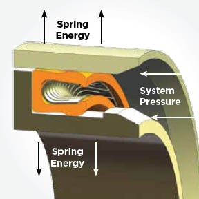
The gland is the machined groove in the metal hardware where the seal sits. In the diagram, you can see the E-gap, or extrusion gap. This is a small clearing between the moving and stationary metal parts of the seal. This gap must be kept tight to prevent the seal from extruding or flowing into it under pressure.

The seal jacket is the U-shaped outer body, which, in PTFE spring-energized seals, is manufactured from PTFE. It provides the main sealing interface against the hardware, and the lips of the jack are the points that actually touch the mating surface.

The spring energizer is contained within the jacket, and it provides constant pressure against the jacket lips and provides pressure outward against the gland walls. This pressure, or sealing force, is maintained by the spring-energizer within the jacket and exists even when there is low to no system pressure. As system pressure increases, the jacket enters the U-cup and further augments the spring’s force and the sealing force.

Practical Seal Gland Design Geometry

PTFE is not flexible like elastomers, and that must be taken into account when specifying the gland geometry. First, proper gland width provides the seal with enough clearance to float, and the gland depth strictly controls the interference, and both are critical for providing sufficient axial and radial freedom instead of just simply squeezing the seal into place. 

When the design creates over-compression, the seal will not be able to flex as it should. This leads to increased friction, accelerated jacket wear, and a potential locked condition where the spring cannot compensate for shaft misalignment. Under-compression brings its own set of problems because it will not be able to fully utilize the spring energy. Leakage at low pressures and a delayed response during pressure spikes severely impact the performance of the seal. 

The goal with the design then becomes the achievement of a uniform load distribution that can conform to surface irregularities and maintain the integrity of the seal.

Seal Gland Design: Corner Radii and Lead-In Geometry

PTFE is softer than steel. If you try to shove this plastic seal into a metal bore that has a sharp 90° corner, that corner acts like a knife. It will slice a layer off your seal before the machine even turns on. This can lead to micro-damage that will later present itself as problematic leaks.

Sharp edges are one of the main causes of damage during PTFE seal installation, and this differs significantly from elastomeric seals. PTFE is stiffer, which makes it more likely to suffer a cut from insertion into a metal bore at a 90° angle. The solution is a shallow lead-in chamfer or on-ramp that is around 15° to 20°, and longer than the seal itself. The length is necessary to ensure the seal is fully compressed before it enters the main bore. In addition, the ramp corners must be rounded, and no sharp edges are allowed.

Seal Gland Design: Surface Finish and Hardware Interaction

Because these seals are constantly rubbing against metal, the surface finish of the metal is of utmost importance. If the surface is too rough, it will abrade the seal and lead directly to leakage. On the other hand, if the surface is too smooth (e.g., mirror polish), it will not be able to hold, and the seal will wipe the sealing surface dry. In addition, because PTFE is self-lubricating and forms a transfer film on the sealing surface, the surface cannot be so smooth that the transfer film does not stick. 2 RMS to 16 RMS, depending on what your application is. 

For gases and liquids at cryogenic temperatures, you want a smoother finish with an RMS between 2 and 4. For gases at non-cryogenic temperatures, the recommended surface finish is between 6 and 12 RMS. For liquids, a surface finish between 8 and 16 RMS is sufficient.

In addition, it is important to specify a plunge-ground finish (0° lead) to prevent spiral tool marks from acting as a screw pump that leaks fluid regardless of seal tightness. 

Seal Gland Design: Squeeze, Clearance, and Extrusion Gap Control

Under extremely high pressures, the behavior of PTFE is significantly different from that of elastomers. At extremely high pressures, PTFE is more likely to flow like a liquid to an area of lower pressure. There will always be a small gap between your piston and cylinder wall to prevent them from grinding against each other. This small gap is known as the extrusion gap, or E-gap. If the gap is too large, the pressure will push the heel of the seal into the gap, shredding the seal. This is where careful specifications come in: when specifying the diameter, include a small enough tolerance to ensure that the gap remains small (e.g., smaller than a human hair) even when the parts move.

Conclusion

Seal gland design for PTFE spring-energized seals is a little different from elastomeric seals and involves more focus on aspects such as geometry, lead-in geometry, surface finish, and extrusion gap control. 

If you need help with a PTFE spring-energized seal, our engineers at Advanced EMC are here and ready to help. Contact us today!

by Daniel Mays Daniel Mays No Comments

Pressure Cycling and Pulsation Issues in Polymer Seals

Pressure cycling and pulsation can lead to seal issues like extrusion, blow-by, and fatigue damage. There are, however, some design principles that can address these issues and mitigate their effects. This article takes a look at the issues related to cycling and pulsation and addresses six key design considerations related to them.

Pressure Cycling and Pulsation

Pressure cycling refers to repeated transitions between low and high pressure, including dwell time at each level. Pulsation, on the other hand, is associated with high-frequency pressure oscillations superimposed on the mean system pressure (often pump- or compressor-driven). Pressure spikes are short-duration transients that exceed nominal operating pressure.

Designing polymer seals for cyclic pressure and pulsation is actually a system-level problem. Consideration must go into the material, energization method, gland geometry, hardware stiffness, surface finish, and validation testing.

Seal Issues Related to Pressure Cycling and Pulsation

When polymer seals are subject to pressure cycling and pulsation, the primary design objective becomes the ability to maintain adequate contact stress and sealing integrity throughout the entire pressure waveform while avoiding extrusion, blow-by, and fatigue damage.

Extrusion occurs when the seal is forced into a clearance gap by pressure, like a soft solid getting pushed into a narrow crack. Blow-by takes place when a pressurized fluid or gas leaks past the seal because there is not enough contact stress. Fatigue damage is the progressive cracking or material breakdown that is caused by repeated loading cycles. Note that each individual cycle can be below the material’s one-time strength limit and still result in fatigue damage.

Signs of Pressure Cycling and Pulsation Issues

There are several signs that pressure cycling and pulsation are causing problems. One of the first is early leakage after a very short run-in period. The seal might also experience intermittent leakage that is related to the duty cycle or pump frequency. Another sign of seal problems is the extrusion of the gear lip, torn edges, or nibbling. Finally, backup ring displacement or seal rotation can also be a signal of issues. 

These problems usually show up in hydraulic actuators, pumps, and manifolds, gas compression stage and valve plates, chemical processing skids with pulsation dampeners, and high-cycle test equipment and aerospace pneumatic systems.

Design Tips for Addressing Pressure Issues

Here are some design tips for working with seals undergoing pressure cycling.

Pressure Waveform

In order to mitigate issues with pressure cycling and pulsation, it is important to look at the pressure waveform and not just the peak pressure. For example, document mean pressure, peak pressure, minimum pressure, ramp rate, frequency, and dwell times. Then identify the transient spikes separately from the steady cycles. Once this information has been gathered, map the waveform to the duty cycle and the total number of cycles.

Polymer

Remember to select the polymer family for the seal based on cyclic strength and creep resistance. Filled PTFE offers good creep resistance and extrusion margin. PEEK and PPS options can lead to a higher modulus, better load retention, and improved wear. UHMW-PE offers low friction but lower stiffness. However, keep in mind that the material choice should also be considered with regard to the temperature, media, PV, and allowable deformation.

Spring-Energized Seals

Another excellent option is to utilize spring-energized seals to maintain contact stress when system pressure drops. These seals have pressure-energized lips designed to avoid issues during pressure reversals. In addition, consider the use of dual-acting geometries for bidirectional pressure. And avoid relying solely on squeeze for long-life high-cycle conditions when relaxation is expected.

Seal Gland

When designing the gland, it is important to ensure that the seal is both well-supported and deforms in a controlled manner when subjected to pressure cycling. The compressive fa orce should provide reliable initial sealing force without being so high that excessive creep results over time. Utilize radii and lead-in chamfers to eliminate sharp edges that can result in problematic notches or tears. And when clearances cannot be held tightly, use anti-extrusion features to ensure the pressure cannot force the polymer into a gap.

Backup Ring

Another potential aspect of the design is the use of a backup ring. Its material should be fully compatible with the primary seal and can maintain strength and dimensional stability across the operating temperature range. When deciding between split or solid design backup rings, keep in mind potential issues with rotation and migration during pressure pulsation. 

Surface Finish

Under pressure cycling, the surface and interface details matter significantly. Small leak paths are the potential problems here, and can be addressed. First, the counterface roughness should result in a surface that supports film formation but does not lead to bypass channels or issues with abrasive wear. The lay direction should prevent machining grooves from behaving as micropumps during pressure fluctuations. In addition, if there is a possibility that erosion, wear, or corrosion could affect the roughness over time, use coatings or surface treatment that will stabilize the counterface.

Conclusion

Pressure cycling and pulsation can cause extrusion, blow-by, and fatigue damage. Careful design, however, can mitigate these issues.

If you are working on a seal design that must provide reliable performance when subject to pressure cycling and pulsation, let the polymer seal experts at Advanced EMC help. Contact us today.