I was eight years old when I saw the Challenger blow up during its launch. The infamous NASA Challenger explosion was carefully investigated and could be traced back to an O-ring that failed. In this blog post, we look at what went wrong and one of the lessons we can take away from it.
Challenger
The Challenger mission objective was to launch a second Tracking and Data Relay System (TDRS) satellite into orbit. This objective would enable longer periods of communication between space shuttles and eventually the International Space Station (ISS). Challenger would deploy the TDRS satellite mated to an Inertial Upper Stage (IUS). This stage would boost it from low Earth orbit to geostationary orbit. In addition, a space walk was planned along with a variety of science experiments.
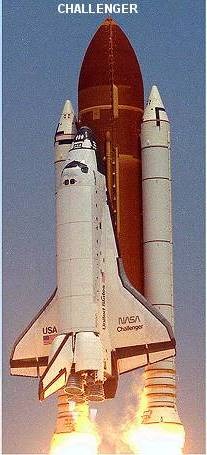
The Challenger Disaster
The infamous disaster on January 28, 1986, can be traced to a failed seal at the aft field joint of the right solid rocket booster. The purpose of the rocket boosters was to propel the orbiter upward during launch and then fall away during ascent. A later study of the footage showed a puff of smoke from this area less than 1 second into the flight, leading to its explosion 73 seconds later.
The disaster cost the lives of the seven astronauts on board — Gregory Jarvis, Judith Resnik, Dick Scobee, Ronald McNair, Mike J. Smith, Ellison Onizuka, and special guest Sharon Christa McAuliffe — and one NASA engineer named Elmer Thomas who died of a heart attack.
Investigating Committee
President Ronald Reagan commissioned a committee known as the Rogers Commission to find the root cause of the disaster. This committee included renowned physicist and Nobel laureate Richard Feynman and astronaut Sally Ride. The team identified the physical cause of the disaster within about one to two weeks of beginning its work, then delivered a comprehensive final report just over four months after the accident
The committee uncovered a great deal of miscommunication between NASA and its subcontractors, as well as inexcusable decisions on NASA’s part and other failures within NASA’s own policies. They also tracked down the physical cause of the failure.
The Notorious O-Ring
The ultimate cause of the explosion was found to be an O-Ring that did not possess the correct low-temperature performance needed. In fact, just eight days after the commission was formed, Feynman famously demonstrated during a televised public hearing that the O-Ring material lost its resiliency when submerged in a glass of ice water. Due to the cold temperatures at launch and the possible presence of frozen water in the solid rocket motor joints, the O-rings were slow to return to their proper shape.
Basically, temperatures were below the glass-transition temperature for the O-ring material, causing it to behave as a brittle material rather than a ductile one and this low temperature also caused it to compression set at that much lower temperature. This destroyed the ability of the o-ring seal to follow the joint gap when pressurized.
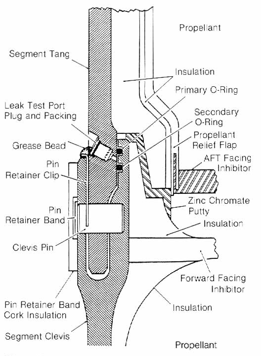
By Rogers Commission into the loss of the Space Shuttle Challenger – http://history.nasa.gov/rogersrep/v1ch4.htm, Public Domain, https://commons.wikimedia.org/w/index.php?curid=107789463
Here is a summary of what happened:
- The solid rock boosters (SRBs) were built in cylindrical segments joined at “field joints.” These field joints were sealed by two Viton FKM O-rings (primary and secondary) rather than a one-piece, welded casing. This was found to be a cost/reusability decision made under the pressure of a fixed-price contract.
- Under internal pressure at ignition, the steel joint segments in the SRBs flex and slightly separate. This was referred to as joint rotation, and it opened a gap. That gap required an O-ring to seal it by expanding quickly enough into it to maintain contact.
- The temperature at the O-ring that morning was 28°F. This was colder than the lowest temperature the shuttle had ever been tested at prior. Below its glass transition range, the fluorocarbon rubber used for the O-ring stiffened and was unable to spring back to close the gap in time.
- Because the primary O-ring was unable to seal the gap in time, hot combustion gas jetted past it. The O-rings were unable to seal the aft field joint on the right solid rocket booster. This caused pressurized hot gases and even flames to “blow by” the O-ring … And reach the adjacent external tank. That flame plume burned through the external tank strut, igniting the liquid propellant and breaking the vehicle apart barely a minute after liftoff.
What makes this disaster even more tragic is that test data had demonstrated a potentially fatal flaw in the O-rings, but NASA and the SRB manufacturer, Morton Thiokol, did not address it. The night before the launch, Thiokol engineers tried to raise the alarm. They were ignored.
Failure Blamed on Design
The conclusion of the committee was that the failure was caused by a design that was far too sensitive to the effects of …
- Temperature
- Physical dimensions
- The character of the materials
- The effects of reusability
- Processing
- Reaction of the joint to dynamic loading.
A Lesson for Modern Engineers
There are a host of lessons to learn from the Challenger disaster, but one in particular stands out to us at Advanced EMC. The choice of material for seals is critical. The O-ring was made of Viton FKM, and it remains a popular choice for seals and O-rings because it is a great material. It just was not the right choice for the Challenger field joints.
Not all materials are equal. They have limits, operating envelopes, and reactivity with other chemicals, and pressure and temperature affect how they function. We cannot choose seal materials solely because basic properties like maximum operating temperature, chemical compatibility, and pressure rating seem to work for the design. But there is more to it than that.
For example, consider a gasket rated for -20°F service that will only ever be tested and characterized at room temperature. This turns out to be the same blind-spot category that doomed the Challenger SRB joint. Compression set behavior, glass transition temperature, and low-temperature resilience deserve the same rigor as your upper-temperature and chemical-resistance data. Remember: the failure mode that gets you is almost always the condition nobody thought to test.
Conclusion
If you need a dependable, reliable O-ring or backup ring (BUR), talk to one of the experts at Advanced EMD. Our engineers are ready to help you from the design phase to installation. Contact us today.