Lubrication is widely considered an investment in your equipment. From keeping your bearings well lubricated, keeping the lubricant free from contamination, and dealing with design challenges when the use of a standard lubricant is not feasible, lubrication for bearings can quickly become expensive and time-consuming.
This article focuses on self-lubricating polymer bearings and includes how they work, how they can cut maintenance costs, and examples of their use.
How Self-Lubricating Polymer Bearings Work
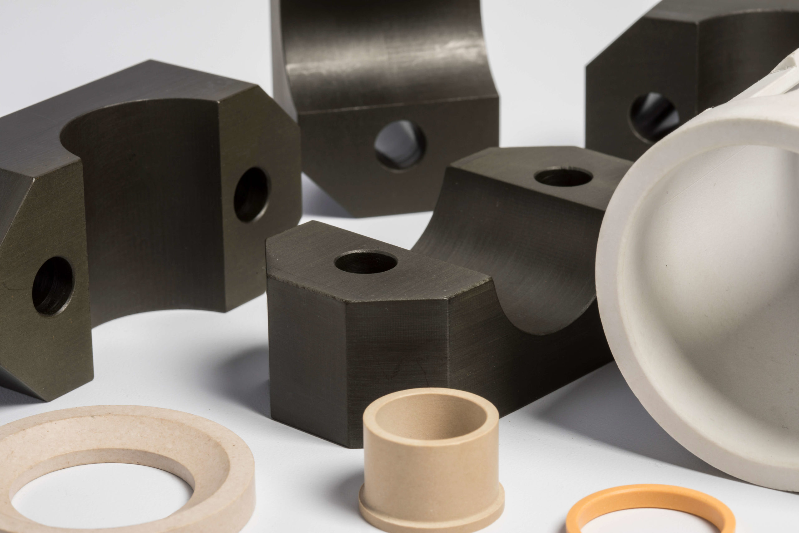
Self-lubricating bearings are made from polymers that either have inherently low friction (virgin PTFE, UHMWPE, acetal, and nylon) or have achieved low friction through the use of internal lubricants (e.g., PTFE fibers, graphite, MoS2). In both situations, wear on the bearing creates an extremely low-friction transfer film on the mating surface. The transfer film serves as the lubricant, eliminating the need for a film or oil and grease.
Self-Lubricating Polymers
Inherently Low-Friction Polymers
- PTFE (Polytetrafluoroethylene): PTFE (Teflon) has one of the lowest coefficients of friction of any solid material, and it can be used on its own or as a liner/filler in composite bearings. The primary drawback of unfilled PTFE is its low load capacity; this makes it common to see reinforced PTFE used for bearings.
- UHMWPE (Ultra-High-Molecular-Weight Polyethylene): This polymer is extremely wear-resistant with good impact strength. Common in food processing and marine applications due to its chemical resistance and FDA compliance.
- Acetal (POM/Delrin): This material is known for being stiff, dimensionally stable, and naturally slippery. Engineers have found it good for lightly loaded bearings and bushings in precision equipment. In addition, it is easy to machine into tight tolerances.
Engineering Polymers Used as Base Materials
- Nylon (PA6, PA66): Nylon is actually a widely used bearing material. It offers good mechanical strength and moderate friction. You may find it oil-impregnated to boost its naturally self-lubricating performance. Nylon does, however, absorb some moisture, which can affect dimensional stability.
- PEEK (Polyether Ether Ketone): PEEK is a high-performance option for extreme temperatures and aggressive chemical environments. And while it is expensive, it is also excellent in demanding aerospace, medical, and industrial applications.
- PPS (Polyphenylene Sulfide): PPS offers good chemical and heat resistance. It is often used as a base material filled with PTFE or graphite for added lubricity.
Filled/Composite Polymer Blends
These are base polymers enhanced with solid lubricant fillers, and often the most practical choice for bearing applications.
- PTFE-filled nylon or acetal: The addition of PTFE dramatically reduces friction and wear compared to unfilled versions.
- Graphite-filled polymers: Graphite adds lubricity and helps in high-temperature or dry-running conditions.
- Molybdenum disulfide (MoS₂)-filled polymers: The addition of MoS2 improves wear resistance, especially under heavy loads and low speeds.
- Carbon fiber-reinforced PTFE: Carbon fiber adds both mechanical strength and overall load capacity while retaining PTFE’s extremely low friction.
How Self-Lubricating Polymer Bearings Cut Maintenance Costs
Self-lubricating bearings reduce maintenance costs in several areas.
First, they eliminate the time it takes to lubricate bearings because there are no scheduled grease/oil intervals, no technician time, and no specialized tools or fittings required. It also reduces expensive downtime because machines will not have to be taken offline for lubrication. The use of self-lubricating bearings also eliminates contamination-related failures involving oil or grease attracting dust or debris, or degrading over time. This also means fewer premature failures and the costs associated with them.
Self-lubricating bearings also lower the total cost of ownership. Even though the unit cost for these bearings may be slightly higher upfront, savings do accumulate over the bearing’s service life. In addition, there are no environmental issues related to lubricants, such as oil disposal or the risk of lubricant leaks contaminating the product (relevant for food/pharmaceutical) or the environment.
Finally, self-lubricating bearings have predictable wear. This is due in part to the fact that polymer bearings often have more predictable wear curves, making replacement planning easier than reacting to lubrication failures.
Where Self-Lubricating Bearings are Used
As an example of plain bearings, PTFE-lined bushings are commonly used in pumps, conveyors, and hydraulic cylinders. Acetal or UHMWPE thrust washers work extremely well in linear actuators or rotating equipment, and olymer-flanged bearings are often used in packaging and printing machinery, where space is tight and frequent relubrication would interrupt production.
In agricultural equipment and outdoor machinery exposed to dust, dirt, and moisture, self-lubricating pillow block bearings have been found to be an excellent solution to such contamination. Pivot/oscillating bearings used in robotic arms, linkages, and hinges, where movement is intermittent rather than continuous (conditions where grease tends to get squeezed out), greatly benefit from the use of self-lubricating bearing solutions. Marine and outdoor equipment: bearings are available that are resistant to water washout, where grease would fail or wash away quickly.
Food and beverage processing uses FDA-compliant polymer bearings that eliminate the risk of grease contamination on production lines. Medical and laboratory equipment also utilizes clean-room compatible bearings for situations where any lubricant residue is unacceptable.
Self-lubricating bearings are commonly used as automotive and light vehicle components such as throttle bodies, pedal assemblies, and seat adjusters, where lifetime lubrication is a design requirement. Finally, high-temperature industrial ovens and dryers face situations where polymer composites with graphite or MoS₂ fillers outperform designs where conventional grease would burn off or break down.
Conclusion
Self-lubricating bearings save cut maintenance costs in a number of ways, such as eliminating the labor costs associated with greasing, reducing downtime (both planned and unexpected), lowering the cost of ownership, and more. And there are several options available when it comes to self-lubricating bearings, including virgin or reinforced polymers. If you are looking for a self-lubricating bearing solution, contact the experts at Advanced EMC today.