A seal rarely fails in isolation, but this is often forgotten. When leakage occurs, the immediate reaction is often to blame the seal itself. However, this approach frequently addresses the symptom rather than the disease. In many failure analyses, the seal is the casualty of a compromised environment.
High-performance spring-energized seals do not function in an environment by themselves. Rather, they are dynamic elements within a complex mechanical system that continuously react to issues in hardware, surface finish, alignment, pressure, and thermal cycling. When these boundary conditions drift outside their engineering limits, even the most advanced spring-energized seal will inevitably fail.
To achieve genuine reliability, the conversation must shift from “seal failure” to “system integrity.”
The Tribological System
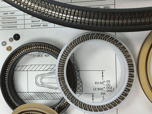
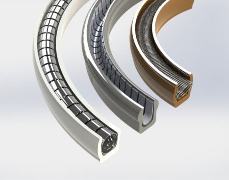
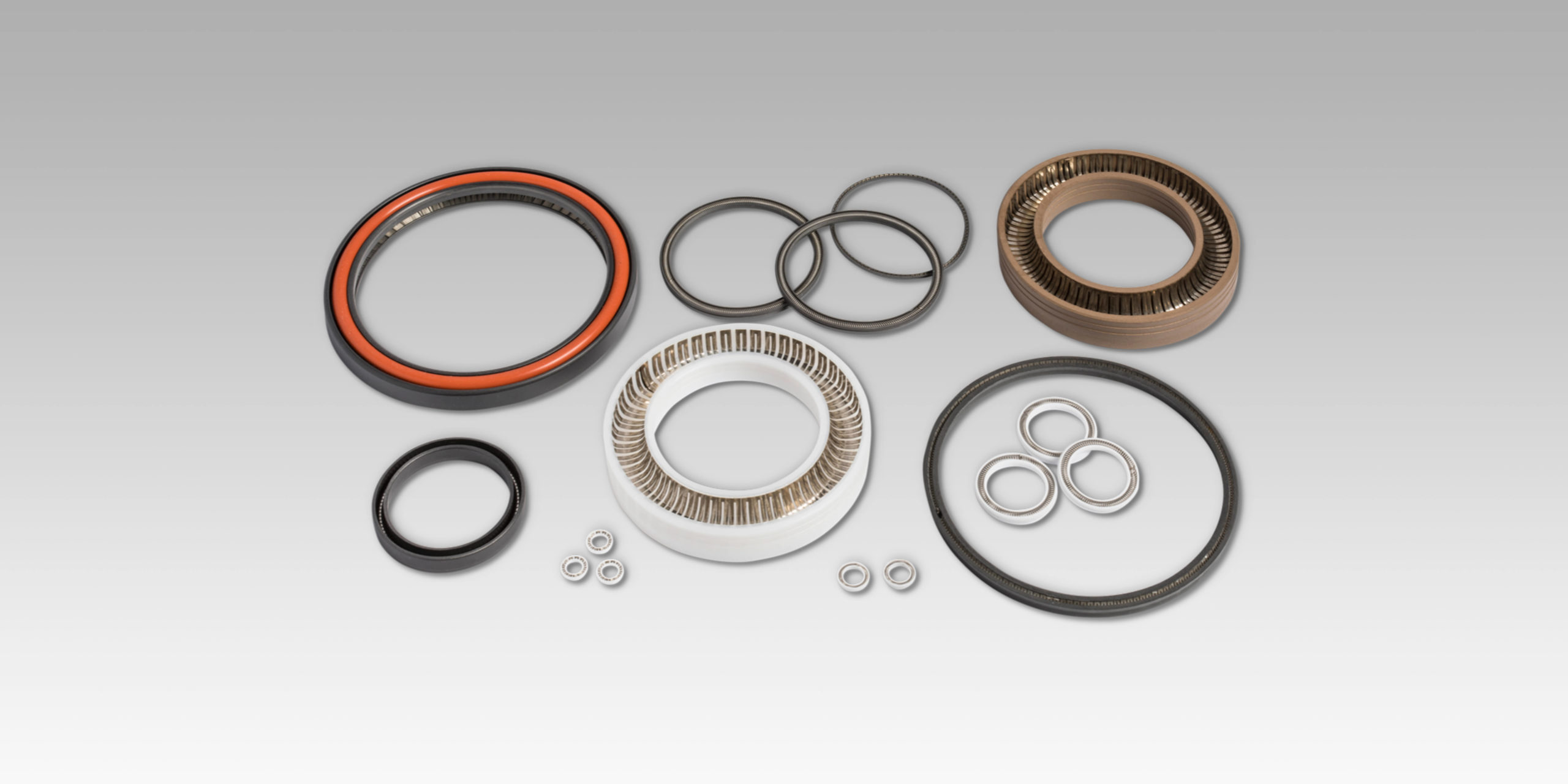
A spring-energized seal is more than a polymer ring with a metallic energizer: it is a critical component of a tribological system. As such, its performance can be directly linked to three factors:
- Gland Design: Dimensions, geometric tolerances, and extrusion gaps
- Counterface: Material hardness, coating integrity, and surface finish
- Operational Physics: Thermal expansion coefficients (CTE), pressure-induced hardware deflection, and friction-generated heat
Each factor impacts the contact stress profile and wear mechanics, which means if one element is ignored, the seal attempts to compensate until the application’s physics overwhelm it.
Gland Geometry for Spring-Energized Seals
The gland design sets the boundary conditions for the spring-energized seal’s life.
Radial Squeeze & Contact Stress: A lack of compression can lead to the formation of spiral leakage pathways in dynamic applications, while excessive interference generates frictional heat and accelerates natural abrasive wear. For spring-energized designs, the incorrect squeeze distorts the energizer’s force-deflection curve, essentially voiding the design that went into the spring.
Groove Volumetrics: A groove that is too wide allows axial shuttling, where the shaft and seal move axially. This leads to a tilted seal and skewed loading profiles. In addition, a groove that violates fill percentage guidelines restricts thermal expansion, causing stress spikes.
Extrusion Gap Mechanics: Under high pressure, PTFE will exhibit cold flow behavior (which is a material property, not a defect). If the extrusion gap (E-gap) is excessive or expands due to hardware pressure breathing, the polymer will extrude into the clearance. In addition, hardware features like lead-in chamfers are critical. A sharp corner acts as a cutting tool during installation, shaving the seal before it ever sees service pressure.
Surface Finish: The Micro-Interface
Surface finish is far too often the silent killer in dynamic applications. It is not enough to specify smooth, but rather define the correct surface finish required for effective film transfer when using materials such as PTFE or PEEK. Keep in mind that PTFE seals rely on the deposition of a thin transfer film onto the mating hardware to stabilize friction. If the counterface is too rough, it abrades the seal lip. On the other hand, if the surface is a mirror polish, it will prevent lubricant retention or film adhesion, leading to serious issues related to high stick-slip friction. The shaft hardness must also support the load: a soft shaft can suffer from galling or scoring, while a delaminating coating means a jagged, abrasive interface that destroys the seal lip.
Thermal and Mechanical Instability
Polymers and metals behave differently thermally. For example, PTFE is going to expand significantly more than steel given the same temperature differential. If such a CTE mismatch is ignored, rising temperatures can cause the seal to overfill the gland, resulting in higher friction and torque. However, when the PTFE spring-energized seal is subject to cryogenic temperature, it may shrink away from the bore and lose contact stress unless the spring energizer is correctly sized to compensate for this dimensional change.
Mechanically, pressure is not static. Housings breathe, bores distort, and bolts stretch. In cyclic applications, the extrusion gap is a dynamic variable that opens and closes with every pressure spike. This forces the seal to fatigue as it continuously reshapes itself to bridge the changing gap.
Misalignment and Eccentricity
Runout and misalignment are simply unavoidable with a rotary shaft seal for several reasons. Eccentric forces on one side of the seal lead to high compression, while the opposite side of the seal lifts off, losing critical contact. This, in turn, results in localized wear patterns and half-moon extrusion failures. Often, the seal is expected to mask bearing slop or structural deflection, which is actually a band-aid for mechanical instability that should have been resolved at the design stage.
Installation of Spring-Energized Seals
Many seals are destroyed before the machine is even turned on. Installation is a violent event for a simple polymer ring. Forcing a seal to go over threads, sharp shoulders, or through undersized bores can slice the polymer jacket or permanently deform the spring energizer, neither of which is good. Installation can destroy a seal before it has had a chance to perform.
Conclusion
Leakage is not solely a material failure. This thought process ignores the complex interplay of gland geometry, surface finish, and thermal dynamics that dictate performance. Trueseal solution reliability requires moving beyond component replacement and embracing a holistic approach to system integrity.
At Advanced EMC, we engineer tribological solutions. If you need help navigating complex boundary conditions or recurring failures with your PTFE spring-energized seals, let our engineers help you analyze the total application. Contact us today to design a sealing system built for your specific operational situation.