
Auto molding and machining are are different manufacturing processes that both lead to a finished part. Which option is better depends on part design, production volume, material, critical dimensions, tolerance requirements, production economics, and the equipment in which the part will operate.
In this article, we look specifically at PTFE auto moding and machining to discuss when auto molding is the better manufacturing option.
What Is PTFE Auto Molding?
Auto molding, also known as compression molding, uses heated compression and dies to form a near-net-shape polymer part. It is a commonly used manufacturing technique for making thermoset and thermoplastic parts, as well as rubber and composites. It is also one of the oldest plastic forming methods still in use.
The auto molding process starts by placing a pre-measured amount of material (usually in the form of a preheated plug, sheet, or granules) into an open, heated mold cavity. That mold is then closed with a matching upper half. A hydraulic press is used to apply high pressure that forces the material to fill the entire cavity shape.
The combination of heat (typically 250–400°F depending on the material) and pressure causes the material to cure (or vulcanize). The result is permanent cross-links within the PTFE polymer structure that lock it into the desired shape. For compression molding PTFE compounds, pressure, sintering temperature, and dwell time are critical process variables. Typical molding pressures of 3,000–4,500 psi and sintering temperatures in the 685–720 °F range are required, while the dwell time is dependent on part geometry, volume, and machine capability.
Once curing is complete, which can take anywhere from a minute to several minutes depending on part thickness and material, the mold opens and the finished part is ejected. Auto molded parts often require minimal trimming of excess flash material.
What PTFE Machining Does Well
An alternative manufacturing method often used with PTFE is machining. Machining removes excess material to produce the final part and may include processes such as milling, turning, and drilling. This approach is well adapted to situations that involve …
- Prototype and development parts
- Low-volume production
- Designs that are still changing
- Components with highly localized geometry or features
- Parts requiring final sizing, precision finishing, or secondary features after molding
- Jobs where a dedicated mold is not economically justified
A part’s complexity, stock availability, scrap rate, and tolerance demands all impact the cost of machining PTFE parts.
Where Auto Molding Excels Over Machining
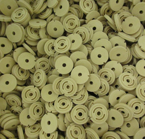
There are, however, several benefits to auto molding. For example, near-net-shape production can reduce material removal and tooling can make sense when demand is stable and sufficient. Auto molding is also a repeatable molding process can support recurring production.
And thick, large, or geometry-specific parts may benefit from being formed closer to finished shape. In addition, molding can reduce subsequent machining, though some finishing may still be required (e.g., machining, facing, drilling, or other finishing operations. Finally, material and process control can be tailored to the specific PTFE compound and part geometry
What are the Real Decision Factors
The table below summarizes the decision factors that are involved.
PTFE Compound Selection Is Part of the Auto Molding Process Decision
Keep in mind that unfilled PTFE and filled PTFE compounds should not be treated as interchangeable. For example, fillers can impact properties such as wear resistance, stiffness, thermal behavior, electrical behavior, friction, and process response. The compound selected should account for factors such as pressure, sliding speed, counterface, media, temperature, chemical exposure, contamination, and dimensional requirements. A manufacturing route should be selected after the material and functional design are understood, not before.
What to Send a PTFE Auto Molder
Here is the type of information that a PTFE molder would need to provide a quote:
- Part drawing and revision level
- 3D model if available
- Material specification or functional requirements
- Critical dimensions and GD&T (Geometric Dimensioning and Tolerancing)
- Tolerances required after sintering and any machining
- Service temperature, pressure, media, and load conditions
- Counterface materials and surface finish for bearing or sealing components
- Regulatory, traceability, inspection, or documentation requirements
- Whether the part is a prototype, bridge-production part, or long-term production design
Conclusion
PTFE auto molding shapes near-net parts under heat and pressure, which both cuts waste and machining time versus starting from stock. Auto molding is the smart choice for recurring, stable-volume production where the molded shape can meet tolerances with minimal finishing; machining, however, is till the preferred choice for prototypes, low-volume runs, or tight localized features.
Not sure which route best fits your part? Send Advanced EMC your drawing, material spec, critical dimensions, and production volume, and our team will help you find the most cost-effective path from design to finished part.