
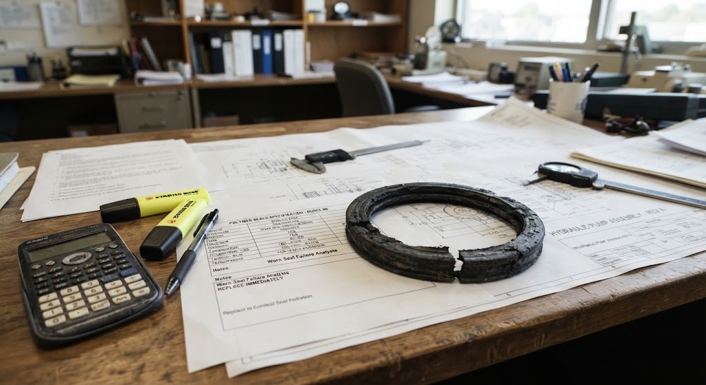
Most spec sheets are organized by material (PTFE, PEEK, FKM), but almost none are organized by what is actually going wrong in a system. That is backward, since seal failure is the symptom you actually have in hand.
This failure-mode guide starts from the failure rather than the catalog. This discussion includes seal extrusion, swelling, pressure trapping, wear, and more. For each failure mode, we discuss what it looks like, its root cause, and what to specify for the material.
What Causes Seal Extrusion
Extrusion looks like chunks torn away or flowing into the extrusion gap, usually on the dynamic/pressure side. Extrusion is really a localized case of creep. Under sustained differential pressure, the seal material behaves less like a solid and more like a very slow-moving fluid, flowing into whatever clearance gap it can find. Higher pressure, larger gaps, and higher temperature (which softens the material and accelerates creep) all speed this up. Keep in mind that elastomers have comparatively low creep resistance: under continuous load they keep deforming rather than settling into a stable state, which is exactly what makes them prone to extrusion.
Thermoplastics like PTFE resist extrusion better than elastomers mainly because they are less elastic, but not because they are immune to creep. Unfilled PTFE, for example, is known for cold flow under sustained load. Filled PTFE compounds (glass, carbon, or bronze) or spring-energized PTFE seal designs are typically specified when extrusion resistance under continuous pressure is the priority. No material choice fully solves an oversized clearance gap; review the design before committing to a material change.
Extrusion and compression set are really two faces of the same creep-driven behavior: one shows up as material flowing away, the other as material failing to recover its shape.
What Causes Seal Compression Set
Compression set is straightforward to spot because it results in a flat-sided cross-section. Compression set results in leakage at low pressure. This can be counterintuitive, because leaks are usually associated with higher pressures. Compression set occurs when a material loses its elastic memory and can no longer rebound over time. It relates to a material’s ability to recover its shape after sustained compression. One fix for compression set is to look for materials engineered for low compression-set values. Also, because compression set develops gradually, it is a good candidate for a preventive replacement schedule rather than reactive repair.
What Causes Seal Hardening / Glazing
Another seal problem is hardening and glazing. When it occurs, the seal will have visible cracking or a glassy/glazed dynamic face, and ties in with a broader loss of elasticity across the whole seal. Two different things can lead to hardening and glazing:
- Excessive speed that generates frictional heat at the face
- Fluid/material incompatibility or sustained high fluid temperature
If hardening or glazing is a problem, look for materials with good heat resistance. Confirm actual continuous-use temperature rating (not just peak rating) against real operating conditions, not catalog optimism.
What Causes Seal Swelling
Swelling occurs when a seal loses its molded shape and may appear larger than the spec. Swelling is fluid absorption (water is the most common culprit) or chemical incompatibility. This is a compatibility problem, not a strength problem, so a stronger material is not the fix. Instead, check a chemical-compatibility chart before specifying a material.
What Causes Seal Scarring
Dents or cuts on the lip of the seal, as well as scratches on the dynamic side, are called scarring. This is usually not a material issue but the result of improper storage, sharp installation tools, or contaminants/scars in the bore or rod. Rather than pursuing a material change, fix the installation practice by supplying proper tools or ensuring the bore is clean, for example. If the scratches can be traced back to contaminated fluid, the system needs flushing. This failure mode does not call for a material or product change.
What Causes Seal Wear
Seal wear is the gradual thinning or degradation concentrated on the seal’s dynamic face, usually from inadequate lubrication or excessive lateral loading. To mitigate premature wear, engineers should consider the friction coefficient and self-lubrication as much as material hardness. The solution to excessive dynamic wear is usually a low-friction, self-lubricating polymer (PTFE, UHMWPE).
What Causes Seal Pressure Trapping and Spiral Failure
Both pressure trapping and spiral failure skew the geometry and design. In pressure trapping, adjacent seals facing the same direction trap fluid, and the fix is a back-pumping design rather than a material change. Spiral failure results when an O-ring twists under long, fast strokes. In this case, the best approach is to fix the geometry (e.g., design a different cross-section) rather than select a new material.
A Seal Decision Framework Quick-Reference
To help you quickly see what to do about the most common seal failure modes, we developed the table below.
| Failure Mode | What You’ll Notice | Root Cause | Material Direction | Is This Actually a Design/Install Issue? |
|---|---|---|---|---|
| Extrusion | Chunks torn away or flowing into the clearance gap, usually on the pressure side | Creep – sustained pressure drives the material into the gap over time | Filled PTFE (glass/carbon/bronze) or spring-energized PTFE over standard elastomer | Partly: oversized clearance gap needs a design review too |
| Compression Set | Flat-sided cross-section; leakage at low pressure | Creep-driven loss of elastic memory | Material engineered for low compression set | No: this is a material property question |
| Hardening / Glazing | Cracking or a glassy dynamic face; general stiffening | Frictional heat from speed, or fluid incompatibility/high fluid temp | Verify actual continuous-use temp rating vs. real operating conditions | Sometimes: check speed/friction before blaming the material |
| Swelling | Soft, shape loss, seal reads larger than spec | Fluid absorption (often water) or chemical incompatibility | Check chemical-compatibility chart before specifying (nylon is prone) | No: compatibility problem, not a strength problem |
| Scarring | Dents/cuts on the lip; scratches on the dynamic side | Improper storage, sharp install tools, or contaminated bore/fluid | Rarely a material fix | Yes: fix installation practice or flush the system first |
| Wear | Gradual thinning concentrated on the dynamic face | Inadequate lubrication or excessive lateral loading | Low-friction, self-lubricating polymer (PTFE, UHMWPE) | Partly: check lubrication/loading alongside material |
| Pressure Trapping / Spiral Failure | Burst at the weaker of two adjacent seals; spiral cuts on an O-ring | Same-direction adjacent seals trap fluid; long fast strokes twist the O-ring | Rarely the fix | Yes: back-pumping design or different cross-section geometry |
Application spotlights
In hydraulic and pneumatic cylinders, extrusion and wear are the primary risks with high pressures and high speeds. Swelling, chemical compatibility, and purity requirements are the primary challenges for semiconductor seal applications. In aerospace applications, hardening and compression set driven by wide temperature swings are among the major challenges. Chemical processing seals often face obstacles with regard to swelling and chemical compatibility.
Conclusion
Seal failures are typically addressed after the fact: a part fails, is replaced in kind, and fails the same way again. The more effective approach is to identify the governing failure mode before specifying a material, not after. Pressure, temperature, chemical exposure, and duty cycle each point to different material requirements; addressing them upfront is more reliable than correcting them after a failure occurs.
For applications where the right material is not clear, our engineering team is available to review your specifications and recommend a solution. Contact us today and let us utilize our knowledge and experience to help you choose the right seal.
